Lower power consumption high gain upper mixer

A mixer and high-gain technology, which is applied in the field of low-power high-gain up-mixers, can solve problems such as gain drop, low gain, and large noise figure, so as to increase load impedance and output signal, and improve conversion Effects of voltage gain and noise figure reduction

Active Publication Date: 2015-05-06
SOUTHEAST UNIV
View PDF4 Cites 0 Cited by
  • Summary
  • Abstract
  • Description
  • Claims
  • Application Information

AI Technical Summary

Problems solved by technology

[0004] The first is the large power consumption. In order to make the mixer circuit have a certain gain to meet the system requirements, its current needs to reach the milliampere level
[0005] The second is the low gain. The gain of the traditional Gilbert mixer largely depends on the size of the load impedance, but the large load impedance will bring too much voltage drop, and due to the existence of parasitic capacitance, at high frequencies The gain will drop sharply. Even if the LC resonant tank with almost no voltage drop is used to generate a large load, it cannot generate a large load impedance due to its limited quality factor.
[0006] The third is that the noise figure is large. Traditional Gilbert mixers input signals from the grid end, and the input impedance seen from the grid end is very large, which matches the output impedance of the previous stage circuit (usually more than 100 ohms) or 50 ohms. Poor, resulting in a large noise figure, difficult to meet the needs of the system

Method used


Image

  • Lower power consumption high gain upper mixer
  • Lower power consumption high gain upper mixer
  • Lower power consumption high gain upper mixer

Examples


Embodiment Construction

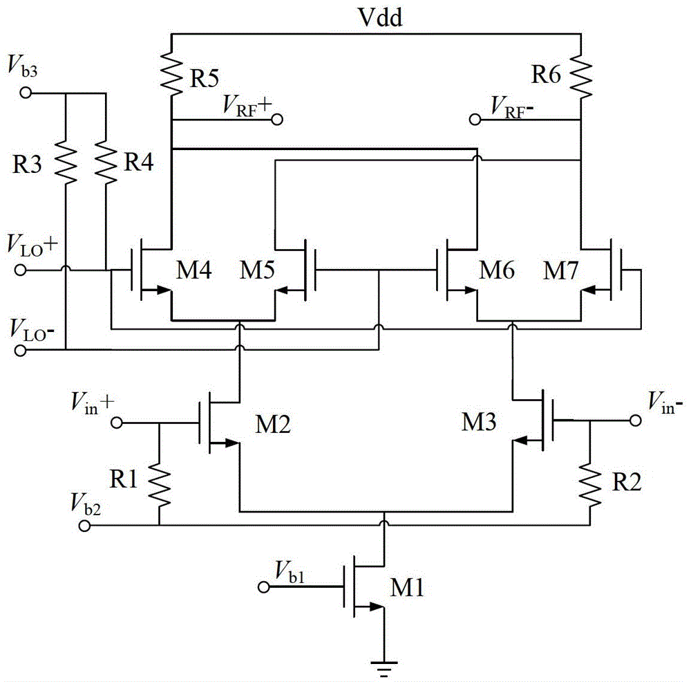
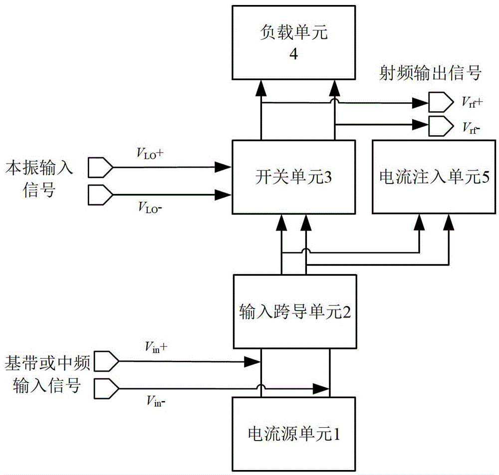
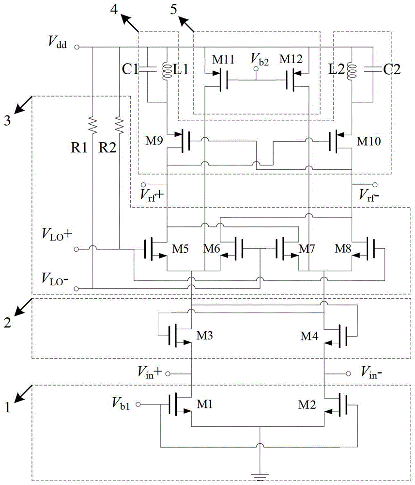
[0032] see figure 2 , the present invention is provided with a current source unit 1 , an input transconductance unit 2 , a switch unit 3 , a load unit 4 and a current injection unit 5 . The positive and negative ends of the differential baseband or intermediate frequency signal V in +, V in- Connect between the current source unit 1 and the input transconductance unit respectively, the output of the current source unit 1 is connected to the input terminal of the input transconductance unit 2, the input transconductance unit 2 amplifies the signal and positively feeds back to itself and then outputs to the switch unit 3 and The current injection unit 5, the output of the switch unit 3 is connected to the load unit 4, and the differential radio frequency output signal V rf +, V rf - Output from load unit 4 and switch unit 3, switch unit 3 and local oscillator input signal V LO +, V LO -connect.

[0033] see image 3 , the current source unit 1 is composed of NMOS tubes,...


PUM


Abstract

A lower power consumption high gain upper mixer comprises a current source unit, an input transconductance unit, a switch unit, a load unit and a current injection unit. An output of the current source unit is connected with the input transconductance unit, and the input transconductance unit amplifies signals and strengthens the signals through positive feedback, then respectively outputs the signals to the switch unit and the current injection unit. An output of the switch unit is connected with the load unit, and difference radio frequency output signals are output between the loading unit and the switch unit. A difference base band or intermediate frequency signals are input between the input transconductance unit and the current source unit, and local oscillator signals are input in the switch unit.

Description

technical field [0001] The invention relates to frequency conversion circuits in various wireless transmitters, especially a low-power high-gain up-mixer, which can be applied to radio frequency transceiver chips, such as wireless local area network (WLAN), wireless sensor network (WSN), Global positioning system (GPS), radio frequency identification system (RFID), Bluetooth system, mobile communication system, mobile digital TV (CMMB, TMMB) and other transceiver chips. Background technique [0002] The up-mixer is generally used as a frequency conversion circuit for various wireless transmitters. Its function is to convert low-frequency signals into high-frequency signals that are conducive to wireless transmission. For most radio frequency transmission systems, the up-mixer is an essential less modules. In order to prolong the service life of the system battery, it is hoped that each module in the transmitter reduces power consumption, and on the basis of reducing power c...

Claims


Application Information

Patent Timeline
Patent Type & Authority Patents(China)
IPC IPC(8): H03D7/12
Inventor 李智群吴晨健陈亮张萌王志功
Owner SOUTHEAST UNIV
Why Eureka
Try Eureka