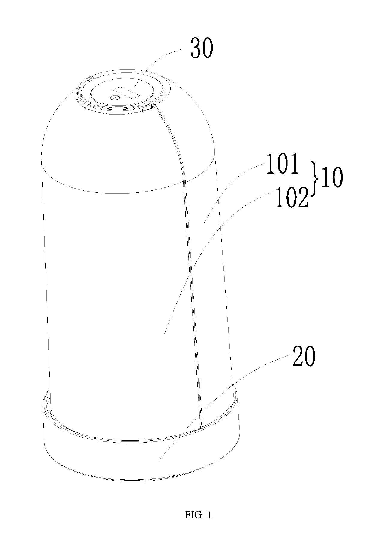
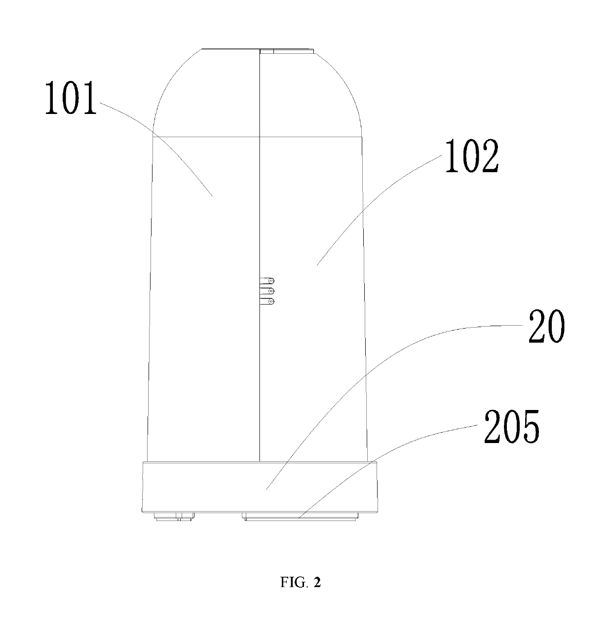
Sterilization box

a sterilization box and box body technology, applied in the field of sterilization boxes, can solve the problems of inconvenient storage of cosmetic tools or daily use items, and achieve the effect of ensuring the cleanliness of cosmetic tools

Inactive Publication Date: 2019-05-07
IPM KOREA CO LTD
View PDF4 Cites 1 Cited by
  • Summary
  • Abstract
  • Description
  • Claims
  • Application Information

AI Technical Summary

Benefits of technology

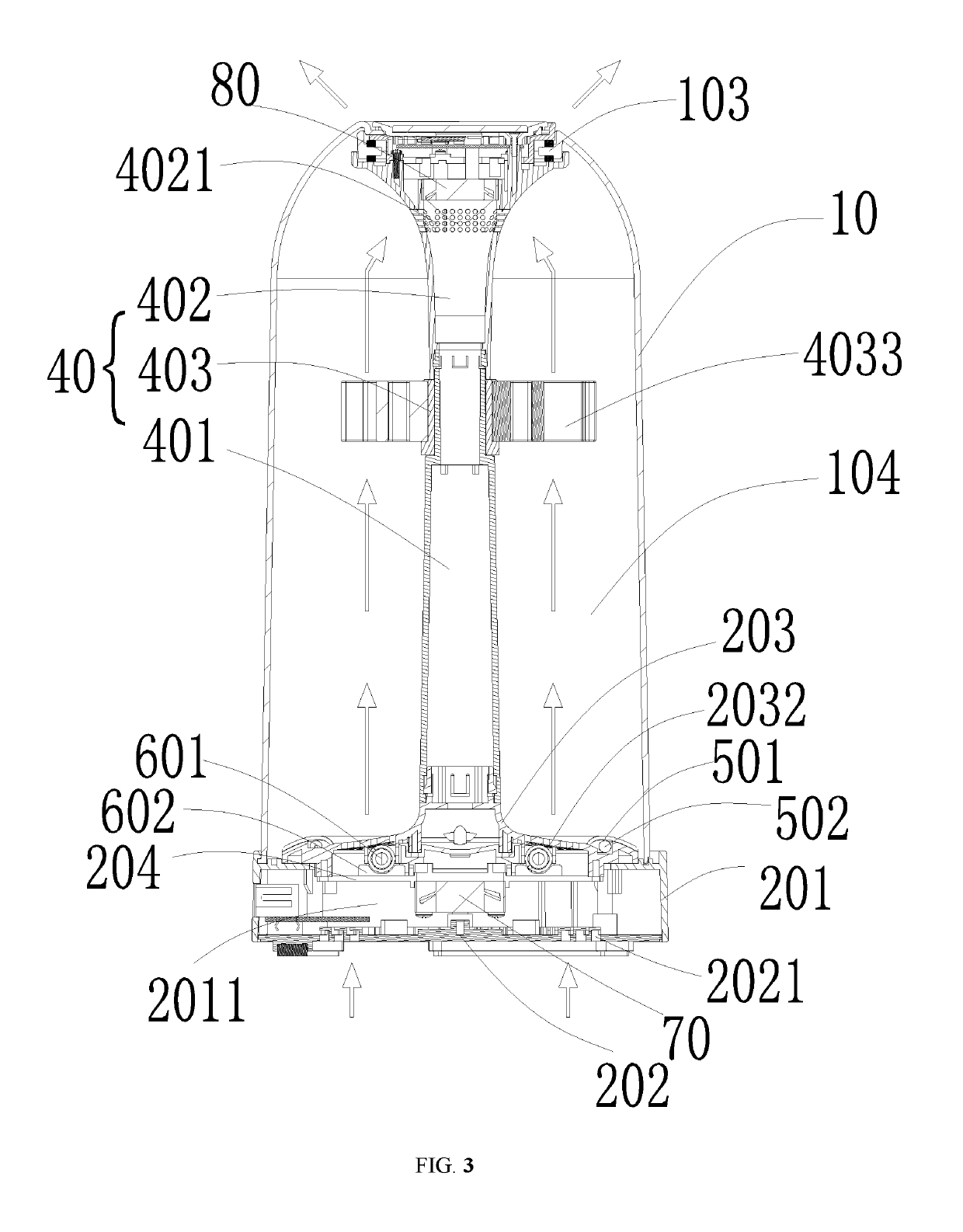
[0015]Compared with the prior art, the sterilized box provided by the present application possesses the following technical effects: the first cavity being able to accommodate multiple cosmetic tools is enclosed by the housing assembly and the base assembly, the base assembly is provided therein with the second cavity, and at the same time the circulation assembly arranged on the base assembly heats and circulates the air in the first cavity and the second cavity via the heating assembly, the first ventilation assembly, and the second ventilation assembly, so as to dry the cosmetic tools after washing. Besides, the first ventilation assembly and the heating assembly cooperate with the second cavity, and the second ventilation assembly cooperates with the first cavity, so that the air entering via the first ventilation assembly is heated and then discharged out via the second ventilation assembly in the upper position, thereby ensuring the dryness of the air inside the first cavity. Meanwhile, the arrangement of the sterilization assembly can also continuously sterilize the cosmetic tools, thereby ensuring the cleanness of the cosmetic tools.

Problems solved by technology

It is one objective of the present application to provide a sterilization box, which aims at solving the problems that in the prior art, the cosmetic tools or the articles for daily use have no dedicated sterilization devices, and that the storage of the cosmetic tools or of the articles for daily use is inconvenient.

Method used


Image

  • Sterilization box
  • Sterilization box
  • Sterilization box

Examples


Embodiment Construction

[0021]In order to make the purposes, technical solutions, and advantages of the present invention be clearer and more understandable, the present invention will be further described in detail hereinafter with reference to the accompanying drawings and embodiments. It should be understood that the embodiments described herein are only intended to illustrate but not to limit the present application.

[0022]It should be noted that when an element is described as “fixed” or “arranged” on / at another element, it means that the element can be directly or indirectly fixed or arranged on / at another element. When an element is described as “connected” to / with another element, it means that the element can be directly or indirectly connected to / with another element.

[0023]It also should be noted that the position terms in the embodiments of the present application, such as “left”, “right”, “on”, “above”, “beneath”, etc., are merely mutually relative concepts or take a normal use state of a produc...


PUM

PropertyMeasurementUnit
timeaaaaaaaaaa
work timeaaaaaaaaaa
structureaaaaaaaaaa

Abstract

The present application belongs to the technical field of household commodity and provides a sterilization box applicable to sterilize cosmetic tools, which comprises a base assembly, a housing assembly connected to the base assembly and cooperating with the base assembly to form a first cavity, and a supporting assembly connected in the first cavity and being able to connect with a plurality of cosmetic tools. The base assembly is provided therein with a second cavity. The sterilization box further comprises a circulation assembly configured to drive air circulations in the first cavity and in the second cavity and a sterilization assembly configured to sterilize the cosmetic tools. The circulation assembly includes a first ventilation assembly cooperating with the second cavity and a second ventilation assembly cooperating with the first cavity. A heating assembly cooperating with the first ventilation assembly is connected in the second cavity.

Description

CROSS REFERENCE TO RELATED APPLICATIONS[0001]This application claims priority to CN 201611059401.X filed Nov. 23, 2016 and is hereby incorporated by reference.TECHNICAL FIELD[0002]The present application belongs to the technical field of household commodity, and particularly relates to a sterilization box.BACKGROUND[0003]In the present household and cosmetic industries, cosmetic tools or articles for daily use, such as small brushes, are involved. Since the cosmetic tools or articles for daily use need to be used every day, and because their use types have particularity, they require to be washed and sterilized frequently. A typical method is performing a drying treatment by sunlight irradiation or using drying devices after washing, however, there is no specific sterilization device for a targeted treatment. Besides, they need to be stored in specific containers after washing and sterilization; at the same time, since cosmetic tools or specific living tools have different use types...

Claims


Application Information

Patent Timeline
Patent Type & Authority Patents(United States)
IPC IPC(8): A61L2/26A61L2/10A46B17/06
CPCA61L2/26A46B17/065A61L2/10A61L2202/20A61L2202/122A61L2202/123A61L2202/182A61L2202/11A61L2/24F26B21/004A61L2202/14A61L2/085A45D2200/10A61L2202/26A61L2202/121A61L2202/17
Inventor LIU, SHUNQI
Owner IPM KOREA CO LTD
Why Eureka
Try Eureka