Stocker

a technology of stocker and airflow, which is applied in the direction of heating equipment, lighting and heating equipment, transportation and packaging, etc., can solve the problems of increasing equipment cost, increasing the power consumption of driving fans, and inability to ensure the cleanliness of storage areas in some cases, so as to reduce equipment costs, facilitate the effect of airflow in storage areas, and reduce equipment costs

Active Publication Date: 2021-01-12
MURATA MASCH LTD
View PDF4 Cites 2 Cited by
  • Summary
  • Abstract
  • Description
  • Claims
  • Application Information

AI Technical Summary

Benefits of technology

[0006]Preferred embodiments of the present invention provide stockers each capable of efficiently forming an airflow in a storage area to ensure cleanliness in the storage area, and reducing or preventing an increase in the temperature in the stocker.
[0009]According to a preferred embodiment of the present invention, it is possible, in the upper portion of the duct, to form an airflow by blowing out air, which is introduced downward from the inlet and the flow of which is regulated by the flow regulator, to the storage area from the blowout openings, and it is possible, in the lower portion of the duct, to form an airflow by blowing out outside air, which is drawn from the fan, to the storage area. With this configuration, it is possible to blow out air at an appropriate flow rate to the storage area across the upper side and the lower side of the duct, and efficiently form an airflow in the storage area to easily maintain the cleanliness in the storage area. Since the upper portion of the duct takes in air from the ceiling fan, it is not necessary to provide many fans across the upper side and the lower side of the duct, equipment cost is able to be reduced and power consumption to drive the fan is able to be reduced. Furthermore, since many fans are not required, it is possible to reduce or prevent an increase in the temperature in the stocker (the storage area).
[0010]In the configuration in which the opening ratios of the blowout openings increase in the upper portion of the duct, from the upper portion toward the lower portion thereof, the opening ratio increases as the flow rate of the air flowing downward decreases, and as a result, it is possible to achieve a uniform or substantially uniform strength of airflow in the storage area, across the upper side and the lower side thereof. In the configuration in which the inlet introduces air, which is caused to flow downward by the ceiling fan provided on the ceiling of the building where the stocker is installed, into the duct, the air is able to be efficiently taken into the duct from the inlet, using the downflow from the ceiling fan.
[0011]In the configuration in which the stocker includes a connection wall extending from an upper portion of the wall to the ceiling, and a lid which closes an upper end of the storage area, air flowing downward from the ceiling fan is able to be efficiently taken into the duct. In the configuration in which the fan blows out the outside air introduced into the duct toward the storage area from the blowout openings, it is possible, in the lower portion of the duct, to efficiently form an airflow in the horizontal direction in the storage area by driving the fan.

Problems solved by technology

However, since the air in the stocker is fed into the duct from the blower motor and blown out to the storage area again, the cleanliness in the storage area may not be ensured in some cases.
This does not only cause an increase in equipment cost as a result of the increased number of fans, but also creates a problem of increased power consumption for driving the fans in the operation of the stocker.
Furthermore, if the number of fans increases, the amount of heat generated as a result of driving the fans will also increase, and this may result in an increase in the temperature in the stocker.

Method used


Image

  • Stocker
  • Stocker
  • Stocker

Examples


Embodiment Construction

[0019]The following describes preferred embodiments of the present invention with reference to the drawings. However, the present invention is not limited to the preferred embodiments. Note that, in the drawings, scale is changed as necessary to illustrate the preferred embodiments, such as by enlarging or by emphasizing a portion.

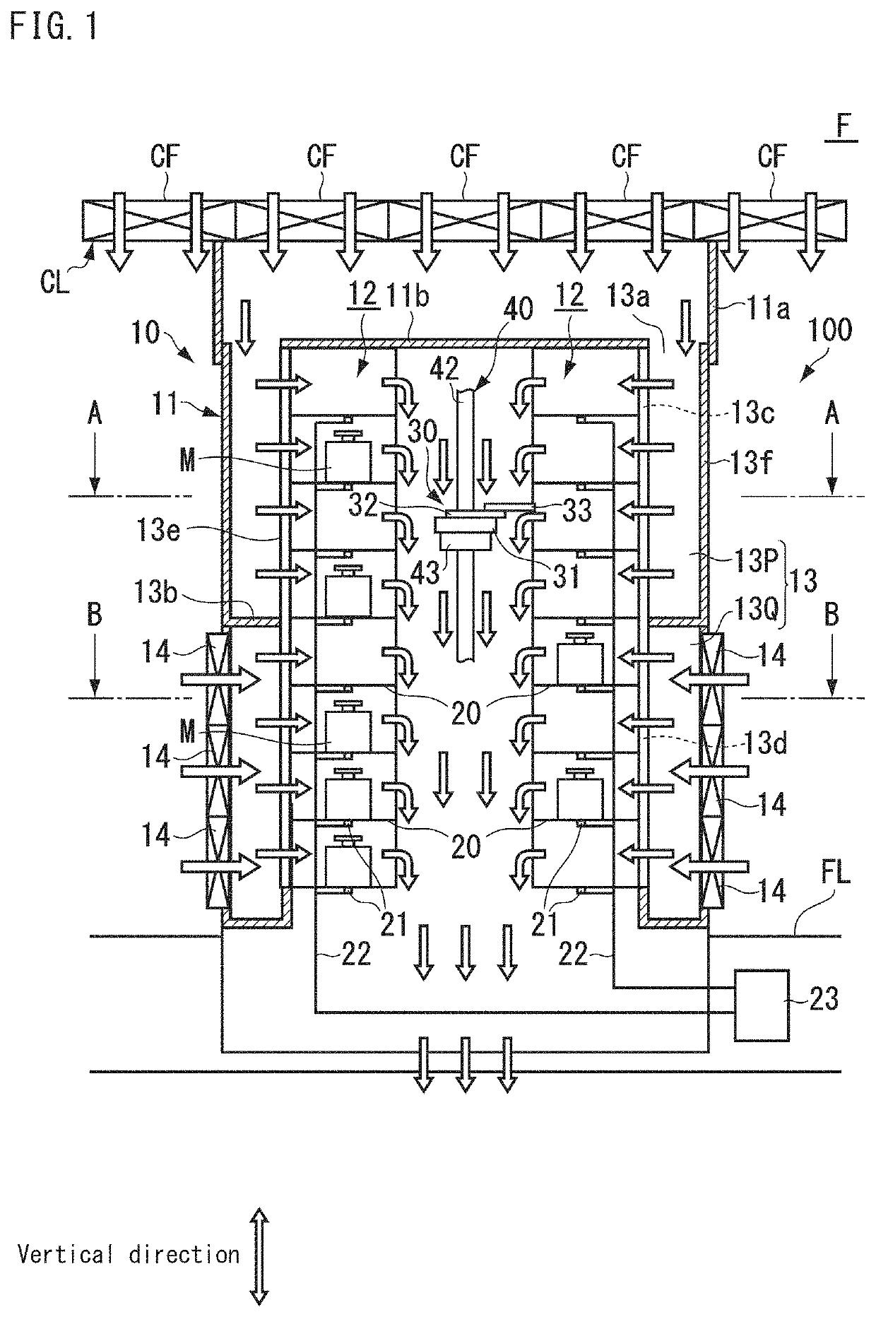
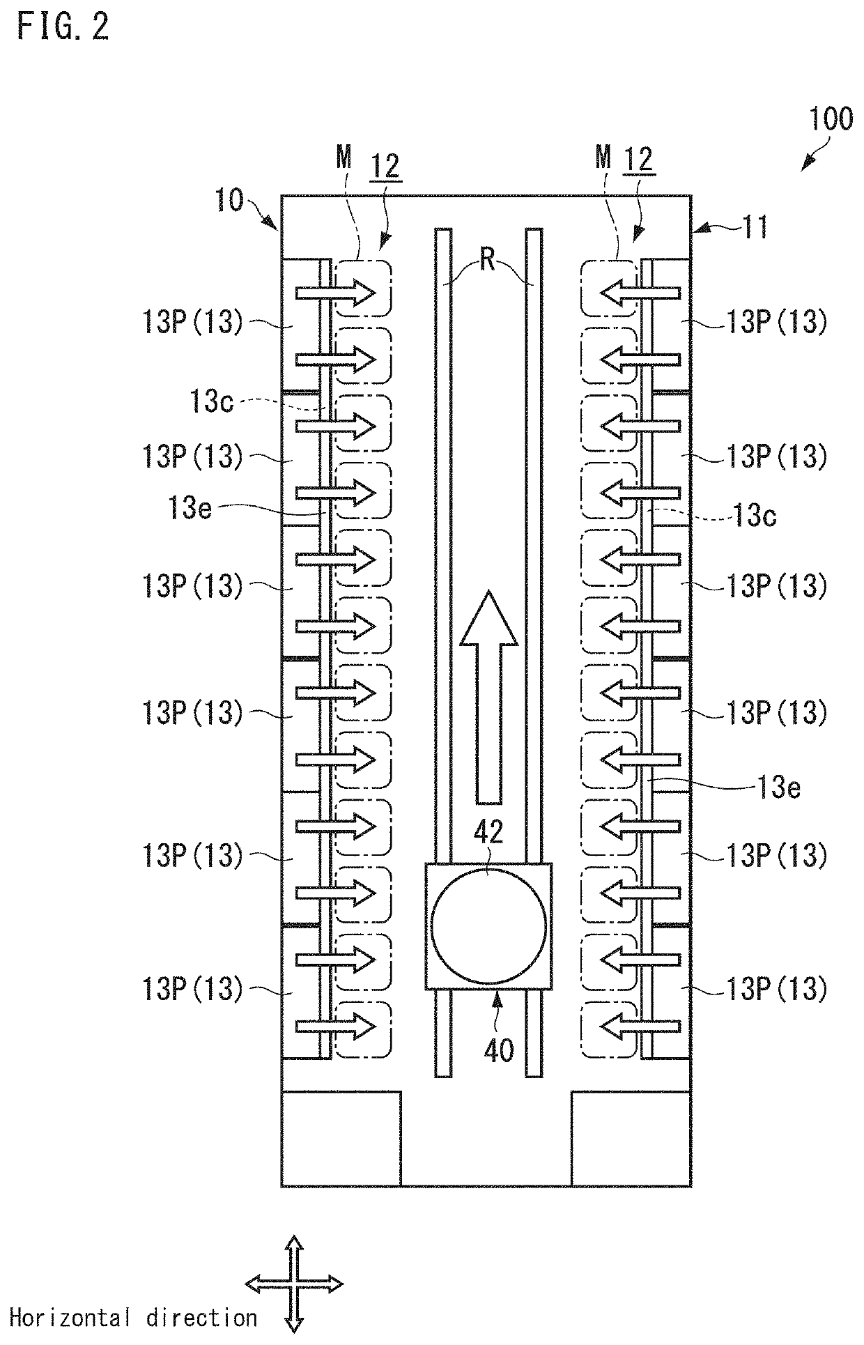
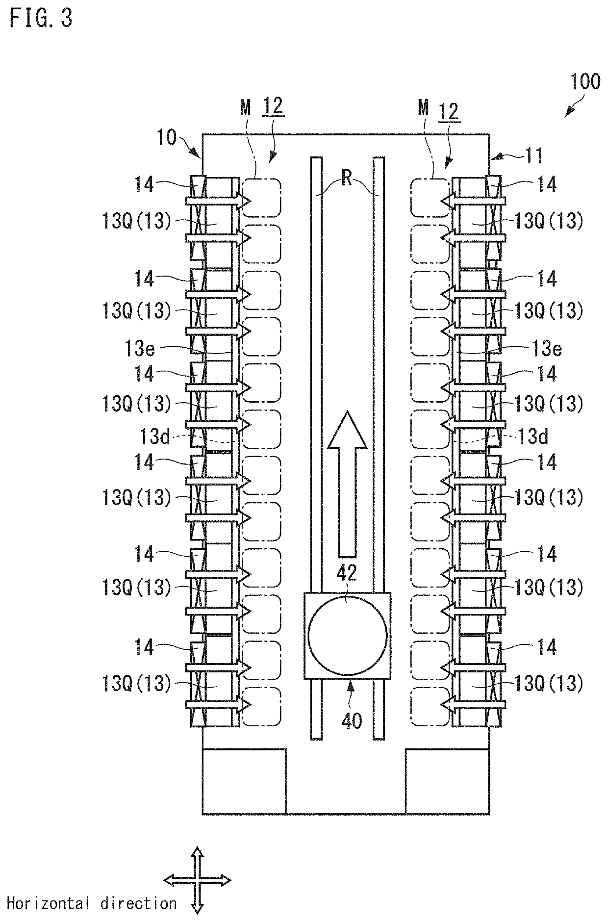
[0020]FIG. 1 to FIG. 3 are diagrams showing an example of a stocker 100 according to a preferred embodiment of the present invention. FIG. 1 shows a cross-sectional view of the stocker 100 as viewed from a side (in a traveling direction of a transporter 40). FIG. 2 shows a configuration in a cross-sectional view taken along the line A-A in FIG. 1. FIG. 3 shows a configuration in a cross-sectional view taken along the line B-B in FIG. 1. As shown in FIG. 1 to FIG. 3, the stocker 100 has a main body 10, racks 20, a conveyor 30, and a transporter 40. The stocker 100 stores articles M inside thereof. In the present preferred embodiment, the article M is, for e...


PUM


Abstract

A stocker includes a wall that separates inside and outside of the stocker, a storage area on an inner side of the wall to store articles, a duct on a wall side of the storage area and extending in a vertical direction, an inlet at an upper end of the duct to introduce air flowing downward into the duct, a flow regulator to regulate an airflow between an upper side and a lower side of the duct, blowout openings on a storage area side of the duct to blow out air to the storage area, and a fan on a lower side of the flow regulator of the duct to draw in outside air and introduce the outside air into the duct.

Description

BACKGROUND OF THE INVENTION1. Field of the Invention[0001]The present invention relates to a stocker.2. Description of the Related Art[0002]A stocker is installed in a semiconductor manufacturing factory or the like in order to store a plurality of containers for accommodating reticles, semiconductor wafers or the like. The stocker has: a wall that separates the inside and the outside of the stocker; and a storage area which is arranged on an inner side of the wall and in which articles are stored. In such a stocker, the cleanliness in the storage area is required to be class 4 or higher in accordance with the ISO standard, depending on the container (or the contents of the container) to be stored. For this reason, clean air from outside is introduced into the storage area to achieve the cleanliness in the storage area. For example, there is known a configuration in which an airflow is formed in the horizontal direction in a storage area, using clean air flowing downward from a ceil...

Claims


Application Information

Patent Timeline
Patent Type & Authority Patents(United States)
IPC IPC(8): B65G1/04F24F3/16H01L21/673H01L21/677
CPCB65G1/04F24F3/161H01L21/67379H01L21/67389H01L21/67769B65G1/00H01L21/673H01L21/67017H01L21/67366H01L21/67393H01L21/67396H01L21/67772H01L21/67775F24F3/167
Inventor KUSAMA, YUGOTO, FUMIKI
Owner MURATA MASCH LTD
Why Eureka
Try Eureka