Crystal-growing furnace with convectional cooling structure

a convection cooling and crystal-growing technology, which is applied in the direction of crystal growth process, polycrystalline material growth, chemistry apparatus and processes, etc., can solve the problems of difficult underside of the crucible, inability to achieve desirable crystal-growing temperature, and inability to cool quickly, so as to save time and improve production efficiency. , the effect of rapid cooling

Inactive Publication Date: 2011-11-22
GREEN ENERGY TECH
View PDF15 Cites 1 Cited by
  • Summary
  • Abstract
  • Description
  • Claims
  • Application Information

AI Technical Summary

Benefits of technology

[0012]Therefore, when silicon slurry is to be cooled and solidified, cooling gaseous stream may flow into a lower portion of the heating room through the central opening. Then the upper opening is opened by the upper door which is driven by the upper driver, so that heated gaseous stream is discharged from the upper opening and flows downward along furnace wall. After having been cooled by the furnace wall, the gaseous stream flows back to the heating room from the central opening. Therefore, an automatic convectional circulating cooling flow field can be formed, such that the silicon slurry can be cooled quickly with time saved and production efficiency improved. Further, in the process of cooling and crystal growing from the silicon slurry, solidification and crystallization starts from bottom to upward of the silicon slurry, such that inner stress and corner fracture may not be occurred to silicon crystal ingots, and that a desirable quality of the silicon crystal ingots can be obtained.
[0013]Further, an inlet tube, having an exit, may be provided in the crystal-growing furnace, where the inlet tube extends deep into the furnace body. The exit is located in, and at the lower part of, the heating room, and adjacent to the central opening, such that argon can be introduced to assure cleanness of gas in the heating room and to improve quality of the silicon crystal ingots.
[0015]Still further, the plural partitions of the heating room are arrayed and fixed to underneath of the upper partition so as to form together an insulating upper-cover structure. The insulating upper-cover structure is fixed to the upper body, while the lower partition is fixed to the lower body. Therefore, when the lower partition moves upward along with the lower body which is attached to the underneath of the upper body, the insulating upper-cover structure can be readily corresponding to and covering on the top of the lower partition. Besides, according to the present invention, the heating room adopts a double-layer structure including an internal insulating layer (such as made of graphite) and an external insulating layer (such as made of alumina fiber). Therefore, the heating room can effect heat insulation through the internal graphite insulation layer, together with warm keeping by the external insulating layer, and that energy can be saved in the process of melting silicon material.

Problems solved by technology

However, the supporting table 914 has a great bulk, and so a relatively great heat capacity, making it difficult for the underneath of the crucible 913, loaded with the silicon slurry, to be cooled despite the cooling gaseous stream.
As a result, the silicon slurry at the bottom of the crucible 913 cannot have a desirable crystal-growing temperature, though the silicon slurry at the upper and side parts, in particular corners, of the crucible has been cooled and thus solidified already.
Such internal stress will now and then cause fracture around the crystal ingots, particularly more serious at the corners of the crystal ingots.
Even if the fracture is not obvious, the crystal ingots or chips might be fractured when a later cutting process is performed.
As a result, the production of crystal ingots fails to have a desirable quality.
Such moving up and down of the insulating cover 911 makes bits of graphite fall into the silicon slurry which thus contains more carbon, and as a result, quality of the crystal ingots of silicon is downgraded.
Further, since the inner wall of the insulating cover 911 rubs against the upper board 910 for quite a long time, a gap between the inner wall of the insulating cover 911 and the upper board 910 becomes greater, and that the situation of heat loss gets seriously day by day.
Nevertheless, such a heat-insulating measure with a thin layer cannot gather heat effectively.
These make the crystal-growing process consume more electricity and time.

Method used


Image

  • Crystal-growing furnace with convectional cooling structure
  • Crystal-growing furnace with convectional cooling structure
  • Crystal-growing furnace with convectional cooling structure

Examples


Embodiment Construction

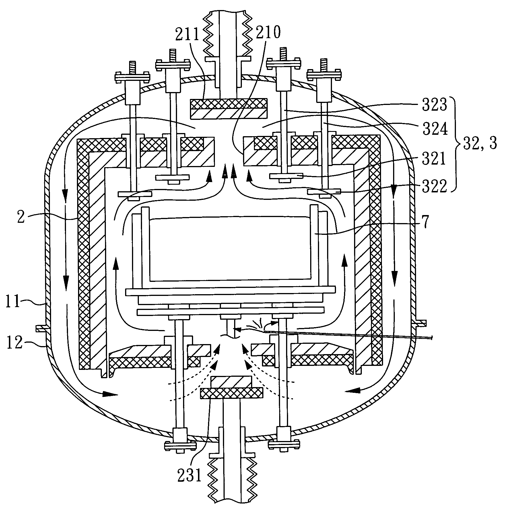
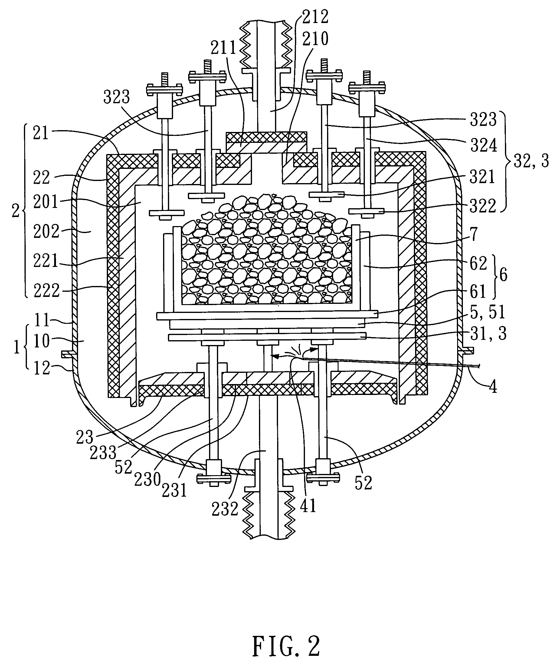
[0025]Referring to FIG. 2, a cross-sectional view illustrating a crystal-growing furnace according to the present invention, the crystal-growing furnace with a convectional cooling structure comprises a furnace body 1, a heating room 2, and at least one heater 3.

[0026]According to the present invention, the furnace body 1 includes an upper body 11 and a lower body 12, wherein the lower body 12 is attached, upward, to underneath of the upper body 11 so as to form an enclosed furnace chamber 10. A heating room 2 is accommodated in the furnace chamber 10 of the furnace body 1, where the heating room 2 includes an upper partition 21, four side partitions 22, and a lower partition 23 which form together an inner space 201. An outer space 202 is defined between the six partitions 21,22,23 and inner wall of the furnace body 1.

[0027]Further, the four partitions 22 of the heating room 2 are arrayed and fixed to underneath of the upper partition 21 so as to form together an insulating upper-c...


PUM

PropertyMeasurementUnit
heat capacityaaaaaaaaaa
crystal-growing temperatureaaaaaaaaaa
internal stressaaaaaaaaaa

Abstract

A crystal-growing furnace with a convectional cooling structure includes a furnace body, a heating room, and at least one heater. The heating room is accommodated in the furnace body, and includes an upper partition, a plurality of side partitions, and a lower partition. The upper partition is provided with an upper opening, and the lower partition with a central opening. Further, the heating room is provided with an upper door, a lower door, an upper driver, and a lower driver. When silicon slurry is to be cooled and solidified, cooling gaseous stream flows into a lower portion of the heating room through the central opening. Then the upper opening is opened by the upper door which is driven by the upper driver, so that heated gaseous stream is discharged from the upper opening and flows downward along furnace inside wall, and flows back to the heating room from the central opening. Therefore, an automatic convectional circulating cooling flow field can be formed, such that the silicon slurry can be cooled quickly with time saved and production efficiency improved. Further, in the process of cooling and crystal growing from the silicon slurry, solidification and crystallization start from bottom to upward of the silicon slurry, such that inner stress and corner fracture may not be occurred to the silicon crystal ingots, and that a desirable quality of the silicon crystal ingots can be obtained.

Description

BACKGROUND OF THE INVENTION[0001]1. Field of the Invention[0002]The present invention relates to a furnace for growing multiple crystals of silicon, more particularly, to a crystal-growing furnace with a convectional cooling structure.[0003]2. Description of Related Art[0004]Referring to FIG. 1, a schematic view illustrating a conventional crystal-growing furnace, a heating room 91 is provided inside the crystal-growing furnace, where an insulating cover 911, a heater 912, a crucible 913, and a supporting table 914 is arranged in the heating room 91.[0005]As shown in FIG. 1, silicon slurry is heated, by the heater 912, to a molten state, and when in a crystal-growing process, the insulating cover 911 is lifted so that cooling gaseous stream can be introduced into the heating room 91 from under the insulating cover 911. However, the supporting table 914 has a great bulk, and so a relatively great heat capacity, making it difficult for the underneath of the crucible 913, loaded with t...

Claims


Application Information

Patent Timeline
Patent Type & Authority Patents(United States)
IPC IPC(8): C30B11/02C30B28/06
CPCC30B11/002C30B11/003C30B29/06Y10T117/1008Y10T117/1024Y10T117/1016Y10T117/10Y10T117/1092Y10T117/1004
Inventor LEW, SHIOW-JENG
Owner GREEN ENERGY TECH
Why Eureka
Try Eureka