Blade and shroud with socket for a compressor of an axial turbomachine

a compressor and blade technology, applied in the direction of engine fuction, climate sustainability, air transportation, etc., can solve the problems of loss of cohesion, complex manipulation of the socket, and inability to suitably place the pla

Active Publication Date: 2019-05-07
TECHSPACE AERO
View PDF10 Cites 0 Cited by
  • Summary
  • Abstract
  • Description
  • Claims
  • Application Information

AI Technical Summary

Benefits of technology

[0047]The present application makes it possible to increase anchoring between the blade and the socket via the fastening layer since it exploits an engagement of material. Fastening is ensured by the shear strength of the layer in addition to its possible adhesive qualities. The blade portion receiving asperities is curved, with the result that its asperities are subjected to differently distributed tension-compression and shear forces. Any breakage in the fastening layer will be able to be more progressive.
[0048]The present application makes it possible to use materials forming a block of material, where appropriate with reduced adhesion. Should a blade or a shroud segment need to be replaced, the removal of the fastening layer is simplified since it hardly sticks. A thermoplastic layer can thus be removed by heat treatment, which reduces or eliminates the necessary physical and / or chemical operations. Any other material melting at a temperature below that of the sockets may be suitable.

Problems solved by technology

However, this technique requires complex manipulations to suitably place each plate.
However, the strength of this connection is limited.
Owing to the vibrations in the turbomachine, loss of cohesion can occur.

Method used


Image

  • Blade and shroud with socket for a compressor of an axial turbomachine
  • Blade and shroud with socket for a compressor of an axial turbomachine

Examples


Embodiment Construction

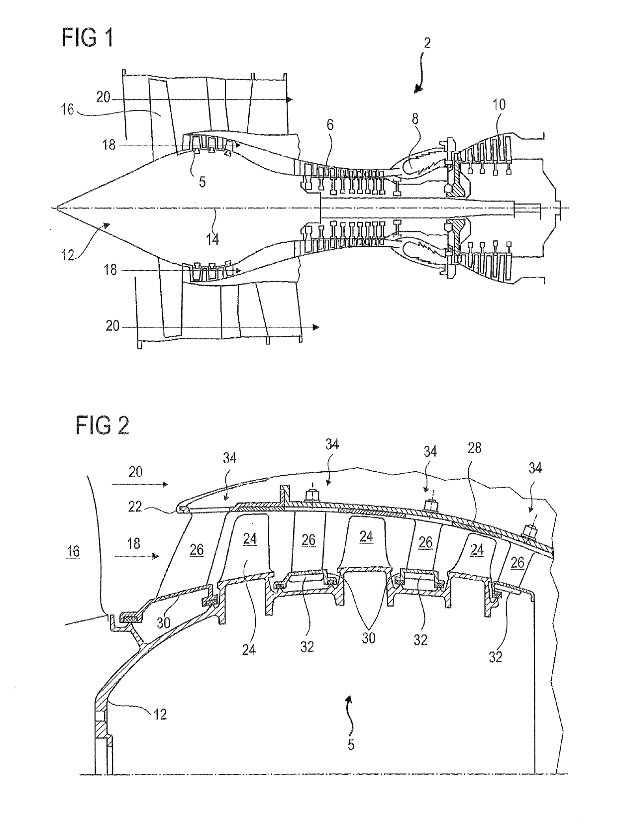
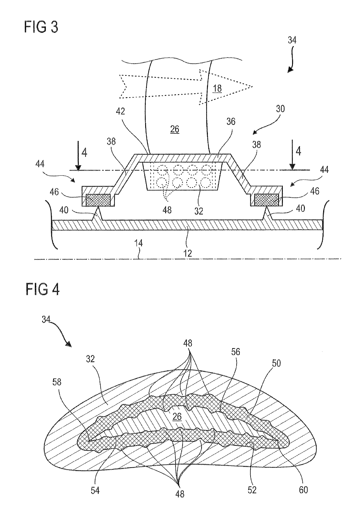
[0013]The present application aims to solve at least one of the problems posed by the prior art. More precisely, an objective of the present application is to improve the fastening of a shroud. Another solution of the present application is to secure the fastening of a shroud with socket to a blade.

[0014]It will have been readily understood that a subject of the present application is a blade of an axial turbomachine, in particular of a compressor of an axial turbomachine, the blade comprising: a wall which comprises: a guide surface intended to radially delimit an annular flow of the turbomachine, and a fastening socket; an airfoil which comprises: a portion fastened in the socket and an aerodynamic portion intended to deflect the annular flow, noteworthy in that it additionally comprises a cementation layer at the interface between the airfoil and the socket so as to fasten the airfoil to the wall by bonding.

[0015]The term “blading” is understood to mean a rigid surface making it ...


PUM

PropertyMeasurementUnit
lengthsaaaaaaaaaa
lengthsaaaaaaaaaa
rotationaaaaaaaaaa

Abstract

The present application is concerned with a blading structure of a compressor of an axial turbomachine for an aircraft. The blading structure includes a wall, such as a composite internal shroud with an organic matrix, which is intended to radially delimit a primary annular flow of the turbomachine and which comprises a fastening socket. The structure additionally has a blade fastened in the fastening socket and extending radially with respect to the wall, and a fastening layer at the interface between the blade and the socket. The interface includes asperities hugging the fastening layer, so as to ensure anchoring by engagement of material in order to fasten the blade in the socket by bonding. The present application also proposes a low-pressure compressor with an internal shroud with sockets bonded to blades.

Description

[0001]This application claims priority under 35 U.S.C. § 119 to Belgium Patent Application No. 2015 / 5316, filed 21 May 2015, titled “Blade and Shroud with Socket for a Compressor of an Axial Turbomachine,” which is incorporated herein by reference for all purposes.BACKGROUND[0002]1. Field of the Application[0003]The present application relates to the fastening by socket of a shroud or of a platform to a blade. The present application is also concerned with a blading structure of an axial turbomachine. Moreover, the present application proposes a compressor and an axial turbomachine, in particular an aircraft turbojet or turboprop.[0004]2. Description of Related Art[0005]A turbomachine comprises a plurality of compartments, including compressors and turbines. The compressors align a plurality of annular rows of stator blades, where appropriate provided with internal shrouds suspended at the internal ends of the aforementioned blades. These shrouds connect a plurality of consecutive b...

Claims


Application Information

Patent Timeline
Patent Type & Authority Patents(United States)
IPC IPC(8): F01D9/04F04D29/16F04D29/02F04D29/32F04D29/64F04D29/54
CPCF04D29/542F01D9/044F04D29/023F04D29/164F04D29/644F04D29/324Y02T50/672F05D2240/11F05D2300/431F05D2300/437F01D9/042F05D2260/36Y02T50/60
Inventor CORTEQUISSE, JEAN-FRANCOIS
Owner TECHSPACE AERO
Why Eureka
Try Eureka