Coupler device and method for using the same

a coupling device and coupling hub technology, applied in the direction of couplings, flanged joints, pipe joints, etc., can solve the problems of large bolts that require large and heavy pre-tensioning equipment, difficult handling, and large bore conduits

Active Publication Date: 2019-05-07
GRANT PRIDECO LP
View PDF19 Cites 0 Cited by
  • Summary
  • Abstract
  • Description
  • Claims
  • Application Information

AI Technical Summary

Benefits of technology

[0022]In one embodiment, the clamping members may be formed with inner inclined clamping surfaces fitting complementary to outer inclined clamping surfaces on the connector hubs for clamping the connector hubs together. Moderate inclination angles, in the range of 7° to 20° may be beneficial for obtaining high amplification effects on the axial preloading between the two connector hubs while still keeping the forces arising from friction at a manageable level.
[0036]In one embodiment, the clamping members may be provided with substantially arc-shaped outer clamping surfaces having an inner radius and an outer radius, wherein the inner radius is substantially equal to that of the radius of the connector hubs. This may be beneficial for quick release of the connector hubs from the clamping members since the clamping members will have to be displaced a minimal distance to release the connector hubs, which may also enable a compact design of the coupler device.

Problems solved by technology

The large bolts generally require large and heavy pre-tensioning equipment.
Clamps for high pressure and large bore conduits are typically large, heavy, and difficult to handle, and it is challenging to obtain an even pressure distribution between the clamp and the connector hubs.
Such coupler devices generally are also quite time consuming to make up, requiring special handling tools.
Both the bolts and the tensioning equipment are typically large and heavy, as well as expensive.
This is especially a handicap for coupler devices assigned for repeated coupling and decoupling during operation, and especially for operations where time is crucial.
A drawback with this solution is that the clamp is unstable when supported by one rod only during the idle conditions prior to connect up.
Further, such an insert ring will not have substantial anchoring for supporting heavy weights prior to connect up.
The insert ring may be troublesome to insert in cases where the pipe line is arranged horizontally, and the handling problems with the clamps will be much the same as for standard clamps without the rods.
Such seal rings may thus easily be damaged during mating operation, and they will only offer a centralizing effect during the last few millimeters prior to “touch down”—and offer no assistance to control of the angular deviation.
Such an insert ring requires two sealing surfaces yielding one additional potential leakage source.
One of the problems with this type of coupler device is free axial access for the connector hub part of the pipe to be connected.
Another challenge with this coupler device is to keep the clamps at a correct axial position relative to the connector hubs during coupling.
At disconnect, after an extended time in operation, the clamps may get stuck and may be hard to release.
According to general uncertainties regarding setting a correct design friction coefficient, there will correspondingly be an uncertainty as to how large the actual preload of the coupler device will be when made up.

Method used


Image

  • Coupler device and method for using the same
  • Coupler device and method for using the same
  • Coupler device and method for using the same

Examples


Embodiment Construction

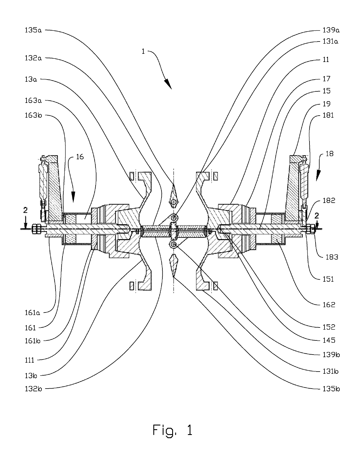
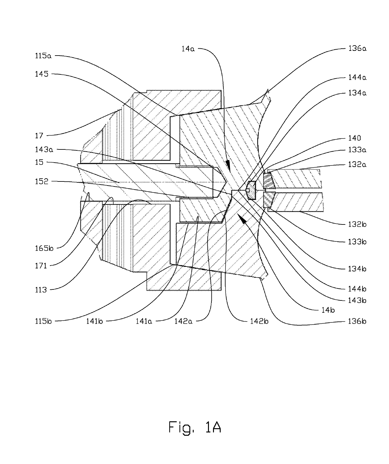
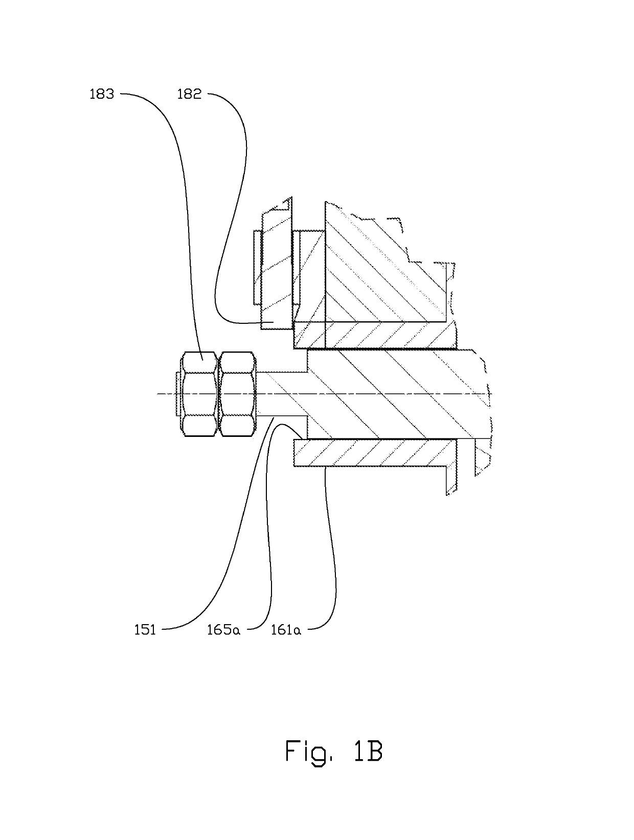
[0061]In the following, the reference numeral 1 denotes a coupler device made in accordance with principles disclosed herein. Identical reference numerals refer to identical or similar components. Most of the figures, except FIGS. 1A, 1B, are symmetrical or close symmetrical about one or two axes in the paper plane. For clarity and for avoiding too many reference numerals on each figure, identical or similar components are numbered only once per figure.

[0062]In FIG. 1, a cross-sectional side view of a coupler device 1 is shown. The coupler device 1 comprises a first connector hub 13a and a second connector hub 13b. The two connector hubs 13a, 13b are configured to be connected to first and second pipe bodies (not shown) by means of connection flanges 131a, 131b. The coupler device 1 of FIG. 1 is shown in a first position clamping the two connector hubs 13a, 13b together by means of a clamp comprising two spaced apart clamping members 11. The coupler device 1 further comprises two cl...


PUM


Abstract

A coupler device for coupling first and second pipe bodies and a method for using the coupler device are disclosed, the coupler device including—a first connector hub configured to be connected to the first pipe body;a second connector hub configured to be connected to the second pipe body;a clamp configured to clamp the first and second connector hubs together, the clamp comprising two or more clamping members; andtwo or more clamping rods, along which the clamping members are configured to be displaced, wherein the at least two clamping rods are rigidly connected to the first connector hub.

Description

CROSS-REFERENCE TO RELATED APPLICATIONS[0001]This application is a 35 U.S.C. § 371 national stage application of PCT / NO2013 / 050092 filed May 22, 2013 and entitled “Coupler Device and Method for Using the Same,” which is hereby incorporated herein by reference in its entirety for all purposes.STATEMENT REGARDING FEDERALLY SPONSORED RESEARCH OR DEVELOPMENT[0002]Not applicable.[0003]The present disclosure relates to a coupler device. More specifically the disclosure relates to a coupler device for coupling first and second pipe bodies.BACKGROUND[0004]A coupler device may be used for, but is not limited to, connecting and de-connecting conduits intended for transfer of pressurized fluids, such as hydrocarbon-containing fluids. Typically, such a coupler device will be used for offloading crude oil or gas from the stern of a floating, production, storage and offloading (FPSO) unit to a shuttle vessel. One part of the coupler device will typically be installed on the shuttle vessel, while ...

Claims


Application Information

Patent Timeline
Patent Type & Authority Patents(United States)
IPC IPC(8): F16L37/62F16L37/30F16L37/00F16L23/04
CPCF16L37/62F16L37/30F16L37/002F16L23/04
Inventor ASKESTAD, SIGMUND
Owner GRANT PRIDECO LP
Why Eureka
Try Eureka