
Optical head and optical disc apparatus

a technology of optical discs and optical head, which is applied in the field of optical head and optical disc apparatus, can solve the problems of destabilizing regeneration signals, difficult to control the values of such phase differences to a desired value, and optical axis shift, and achieves stable output, high signal amplification effect, and easy adjustment of two beam axes

Inactive Publication Date: 2012-01-12
HITACHI CONSUMER ELECTRONICS CORP
View PDF4 Cites 5 Cited by
  • Summary
  • Abstract
  • Description
  • Claims
  • Application Information

AI Technical Summary

Benefits of technology

[0011]An advantage of the present invention is to provide an interference-type optical head and optical disc apparatus that easily adjust the axes of two beams, have a high signal amplification effect, and produce stable outputs.
[0012](1) An optical head according to a first aspect of the present invention includes: a light source such as a semiconductor laser; a polarization splitter such as a polarization beam splitter that splits a beam emitted by the light source into a signal beam and a reference beam; a condenser such as a convective lens that condenses the signal beam on an optical information recording medium and emits the condensed beam; a parallel beam emitter such as a corner cube prism that displaces the reference beam and emits the displaced beam so that the displaced reference beam is in parallel with the signal beam reflected in an opposite direction from the optical information recording medium; a second polarization splitter such as a beam displacer that splits polarization of the signal beam and polarization of the reference beam; a multiplexer that multiplexes the signal beam and the reference beam generated by the polarization splitter to generate a multiplexed beam; an interference beam generator such as a Wollaston prism that generates interference beams of the signal beam and the reference beam from the multiplexed beam; and a detector that detects the interference beams generated by the interference beam generator.
[0013]Thus, it is possible to multiplex the signal beam and the reference beam with the respective optical axis directions determined with high accuracy and thus to obtain amplifies signals stably.
[0014](2) In (1), the parallel beam emitter preferably includes: a parallel beam reflector such as a corner cube prism that displaces the reference beam generated by the polarization splitter and emits the displaced reference beam in parallel; and the polarization splitter, the polarization splitter reflects the reference beam emitted by the parallel beam reflector.
[0015]Thus, even when the signal beam and the reference beam generated by the polarization splitter are emitted in different directions, these beams can be easily made parallel with each other as separated from each other. This reduces the adjustment frequency, reducing the cost of the optical head.
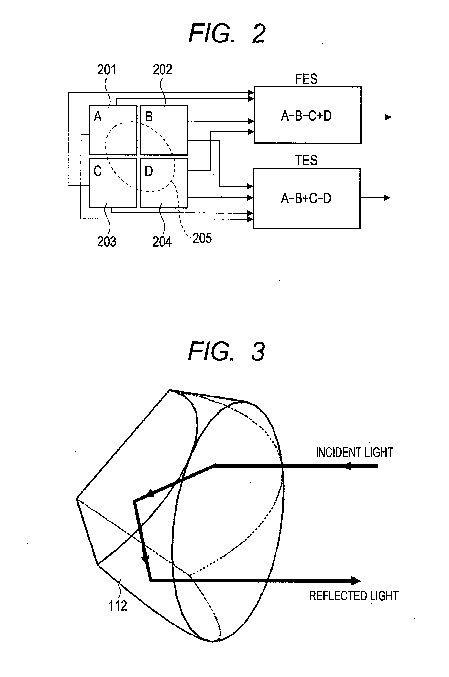
[0016](3) In (2), the parallel beam emitter is preferably a corner cube prism.

Problems solved by technology

However, a slight tilt of the mirror shifts the optical axis, causing an optical axis shift between the signal light and the reference light.
Generally, it is not easy to control the values of such phase differences to a desired value.
This characteristic disadvantageously generates an error in the phase difference between the signal light and the reference light in the generated interference light and thus destabilizes the regeneration signal.
Further, generally, it is difficult to correctly control the split ratio of the non-polarization beam splitter (the intensity ratio between the transmitted light and the reflected light).
While the above-mentioned conventional technology must achieve a split ratio of 1:1 regardless of the polarization state, it actually generates an error and thus unfavorably destabilizes the regeneration signal.

Method used


Image

  • Optical head and optical disc apparatus
  • Optical head and optical disc apparatus
  • Optical head and optical disc apparatus

Examples


first embodiment

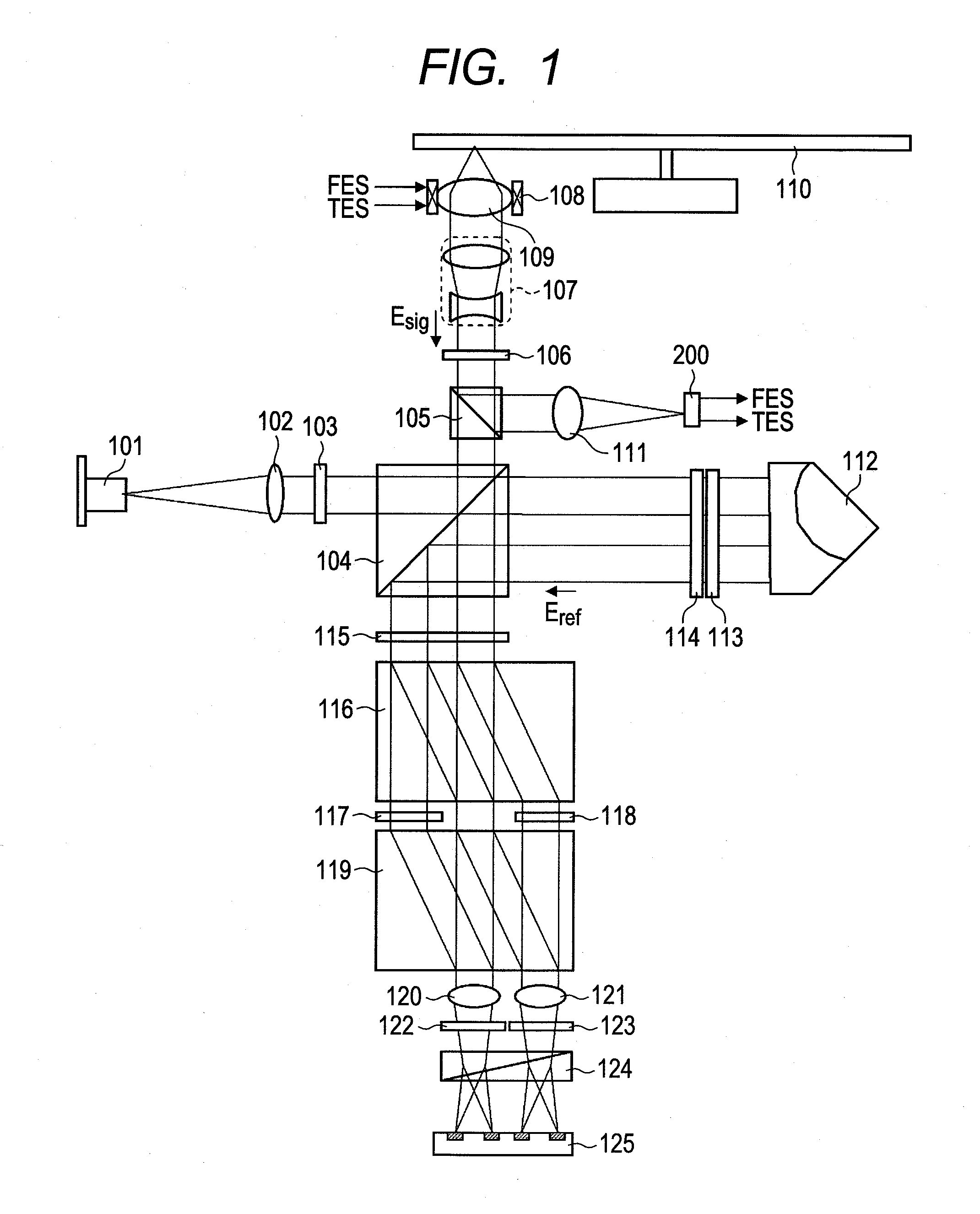
[0053]Now, a first embodiment of the present invention will be described with reference to FIG. 1.

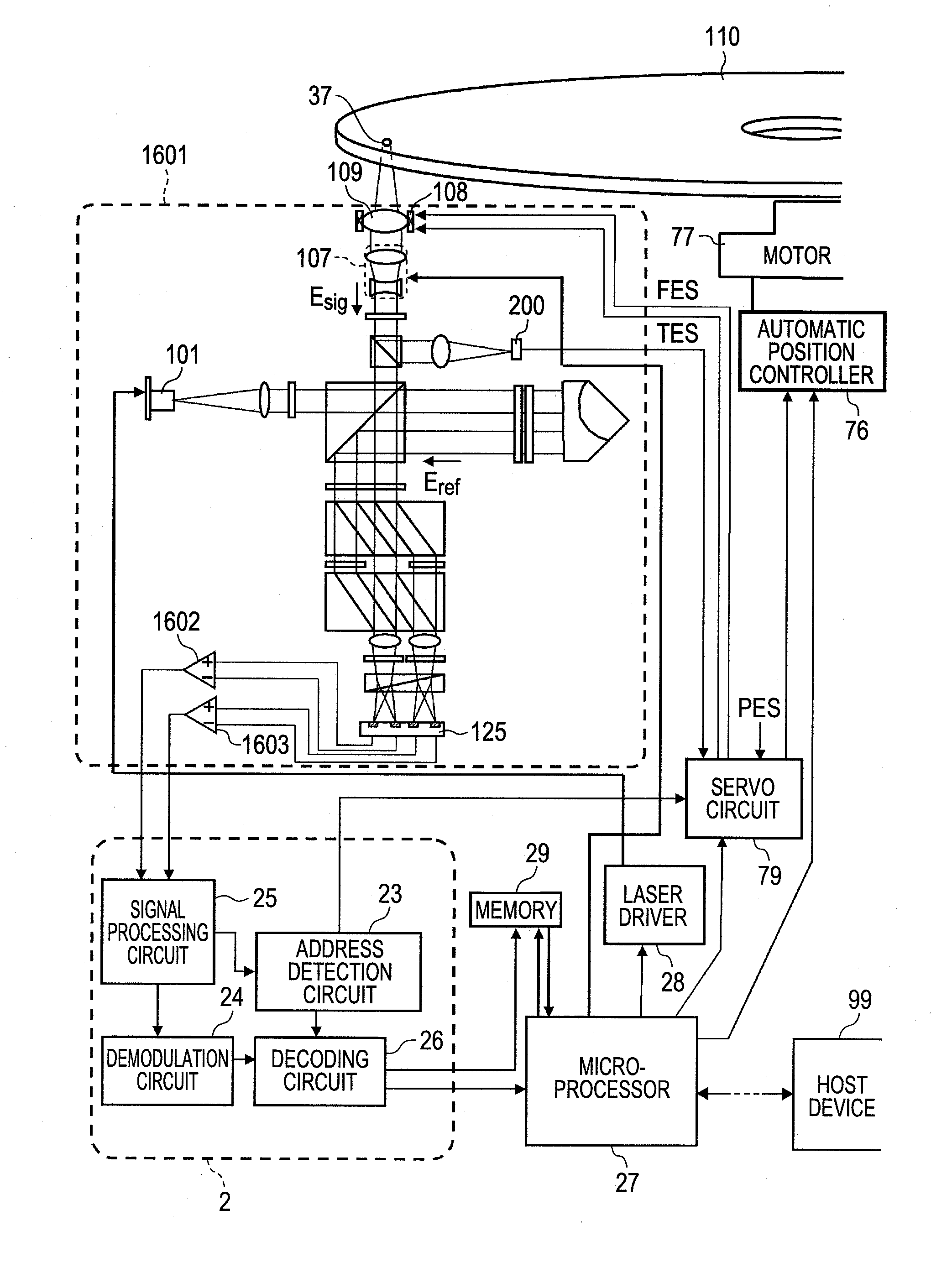
[0054]FIG. 1 shows a basic configuration of an optical head according to this embodiment. Light from a semiconductor laser 101 is converted by a collimate lens 102 into parallel beams, which then pass through a half-wave plate 103 and come into a polarization beam splitter 104. The polarization beam splitter 104 has functions of transmitting approximately 100% of p-polarization (hereafter referred to as “horizontal polarization”) incident on its split surface and reflecting approximately 100% of s-polarization (hereafter referred to as “vertical polarization”) incident thereon. The intensity ratio between transmitted light and reflected light can be adjusted by adjusting the rotation angle of the half-wave plate around the optical axis. The reflected light (hereafter referred to as “signal light”) initially comes into a specialized polarization beam splitter 105. As its characteristics,...

second embodiment

[0068]This embodiment is an embodiment where the signal light and the reference light are multiplexed and then split again. FIG. 10 shows a configuration diagram of this embodiment. As in the first embodiment, the signal light is reflected by the optical disc 110, travels back along the optical path, and passes through the polarization beam splitter 104. On the other hand, the reference light passes through a quarter-wave plate (axis direction: 45° relative to the horizontal polarization direction) 1001, is condensed on a mirror 1003 by a lens 1002, reflected by the 1003, travels along the optical path in a 180° opposite direction, and passes through the quarter-wave plate 1001 again. Thus, the polarization is rotated by 90°. When the reference light is reflected by the polarization beam splitter 104, the signal light and the polarization are multiplexed in a perpendicular state. The multiplexed beam is condensed by a lens 1004 and split by a beam displacer 1005 so that the split be...

third embodiment

[0071]This embodiment is an embodiment where the process of splitting each of the signal light and reference light to cause the signal light and reference light to interfere with each other in different phases and the process of multiplexing the split signal light and reference light are performed simultaneously. FIG. 12 shows a configuration diagram of this embodiment. This embodiment is the same as the first embodiment until the signal light and the reference light pass through a half-wave plate (axis direction: 22.5° relative the horizontal polarization direction) 115. The signal light and the reference light are multiplexed by a polarization beam splitter 1201, and two multiplexed beams go out thereof. The polarization states of the signal light and the reference light at that time are as shown in FIG. 13. The horizontal polarization components of the signal light pass through the polarization beam splitter 1201, as well as are multiplexed with the vertical polarization componen...


PUM

PropertyMeasurementUnit
wavelengthaaaaaaaaaa
reflectanceaaaaaaaaaa
speedaaaaaaaaaa

Abstract

Reference light for interference with signal light from an optical information recording medium is displaced and reflected by a corner cube prism or the like with high accuracy. The signal light and the displaced reference light are made parallel with each other with high accuracy. The signal light and the reference light are each split using a polarization splitter to generate interference light. Thus, regeneration signals are stabilized. Accordingly, an interference-type optical head and optical disc apparatus of higher quality than conventional ones can be provided.

Description

CLAIM OF PRIORITY[0001]The present application claims priority from Japanese patent application JP2010-154138 filed on Jul. 6, 2010, the content of which is hereby incorporated by reference into this application.BACKGROUND OF THE INVENTION[0002]1. Field of the Invention[0003]The present invention relates to increasing of the S / N of regeneration signals of optical disc apparatus.[0004]2. Description of the Related Art[0005]As for optical discs, the resolution of optical systems therefor has almost reached the limit as Blu-ray discs using a blue semiconductor laser and a high-NA objective lens become commercially available. To further increase the capacity thereof, multi-layering of the recording layer is considered to become a predominant method from now on. In such a multilayer optical disc, the amounts of light beam detected from the recording layers must be approximately equal to one another. For this reason, the reflectance from a particular recording layer must be reduced. Howev...

Claims


Application Information

Patent Timeline
Patent Type & Authority Applications(United States)
IPC IPC(8): G11B7/135
CPCG11B7/005G11B7/0051G11B7/1381G11B7/1359G11B7/1356
Inventor MIKAMI, HIDEHARU
Owner HITACHI CONSUMER ELECTRONICS CORP
Learn More