Optical disk apparatus

a technology of optical disc and readout signal, which is applied in the direction of data recording, instruments, disposition/mounting of heads, etc., can solve the problems of difficult to put techniques into practical use, the method of adjusting the optical path difference between the two lights is not particularly described, and the miniaturization of the optical system is not suitable for miniaturization. achieve the effect of high signal amplification effect, facilitate the control of optical path differences, and facilitate the miniaturization of the optical system

Inactive Publication Date: 2010-05-11
HITACHI LTD
View PDF11 Cites 4 Cited by
  • Summary
  • Abstract
  • Description
  • Claims
  • Application Information

AI Technical Summary

Benefits of technology

[0009]In consideration of the conventional techniques described above, it is an object of the present invention to provide an optical disc apparatus including an interference-type optical disk signal detection system, which facilitates the control of an optical path difference between two lights, which has a high signal amplification effect and which is suitable for miniaturization of an optical system.
[0010]In order to facilitate the control of the optical path difference, as one aspect of the present invention, the optical system is integrally formed, and the entire optical system is driven relative to a disk in an optical axis direction by autofocus drive. Accordingly, as in the case where only an objective lens is moved by autofocus control, the optical path length in the optical system is no longer changed. Thus, the control range of the optical path difference can be narrowed to facilitate the control thereof. There have heretofore been proposed various optical heads, in each of which the optical system is integrally formed, and which the entire system is driven in a focus direction. However, a fundamental object thereof is not to fix the optical path length, but to facilitate manufacturing thereof by eliminating a focus actuator from a very small optical head. Meanwhile, in the present invention, the optical system is integrated to achieve a higher signal-to-noise ratio in the interference optical system.
[0011]By using the Twyman-Green type optical system as the interferometer but not the Mach-Zehnder type, the optical system is miniaturized, and the number of beam splitters is reduced, thereby the costs can be lowered. In the conventional techniques described above, the reason for not using the Twyman-Green type interference optical system is assumed to be because it is required to insert a half wave plate in one-way optical path in order to control a polarization direction of light causing interference with the polarization rotation light on the magneto-optical disk. However, for the optical disks without polarization rotation, such as a phase change optical disk and a Read-Only Memory type optical disc (ROM optical disc) having uneven pits, the Twyman-Green type optical system enables the formation of a smaller optical system. For the formation of the Twyman-Green type optical system, a polarizing beam splitter is used, and quarter wave plates are inserted in both optical paths of the transmission side and the reflection side of the polarizing beam splitter for the initial incident light. Accordingly, both of light reflected from the disk and light reflected from the reference mirror can be obtained without any losses, in principle, to travel toward a second polarizing beam splitter for differential detection. In this event, the polarization directions of the two lights are orthogonal to each other. The two lights cannot interfere with each other as they are. Thus, by use of half wave plates and the like, the lights are made incident so as to be tilted at 45 degrees relative to the main axis direction of the second polarizing beam splitter. Accordingly, the transmitted light and the reflected light are allowed to interfere with each other while aligning polarizations respectively. Thus, the differential signal having detected intensity is set to be a detection signal.
[0012]According to the present invention, it is possible to provide, at low cost, an optical disc apparatus including an interference-type optical disk signal detection system, which facilitates control of an optical path difference between two lights, which has a high signal amplification effect, and which is suitable for miniaturization of an optical system.

Problems solved by technology

Each of the optical systems of interferometers used in the conventional techniques described above is a Mach-Zehnder type optical system, which is not suitable for miniaturization of the optical systems due to a large number of optical parts.
Furthermore, as another problem, a method for adjusting an optical path difference between the two lights is not particularly described in the foregoing documents.
Thus, it is difficult to put the techniques into practical use.
However, this solution is intended to propose a new disk standard, and is not intended to achieve a higher signal-to-noise ratio in the existing disk.

Method used


Image

  • Optical disk apparatus
  • Optical disk apparatus
  • Optical disk apparatus

Examples


embodiment 1

[0023]With reference to FIGS. 1 to 5, Embodiment 1 that is a basic embodiment of the present invention will be described.

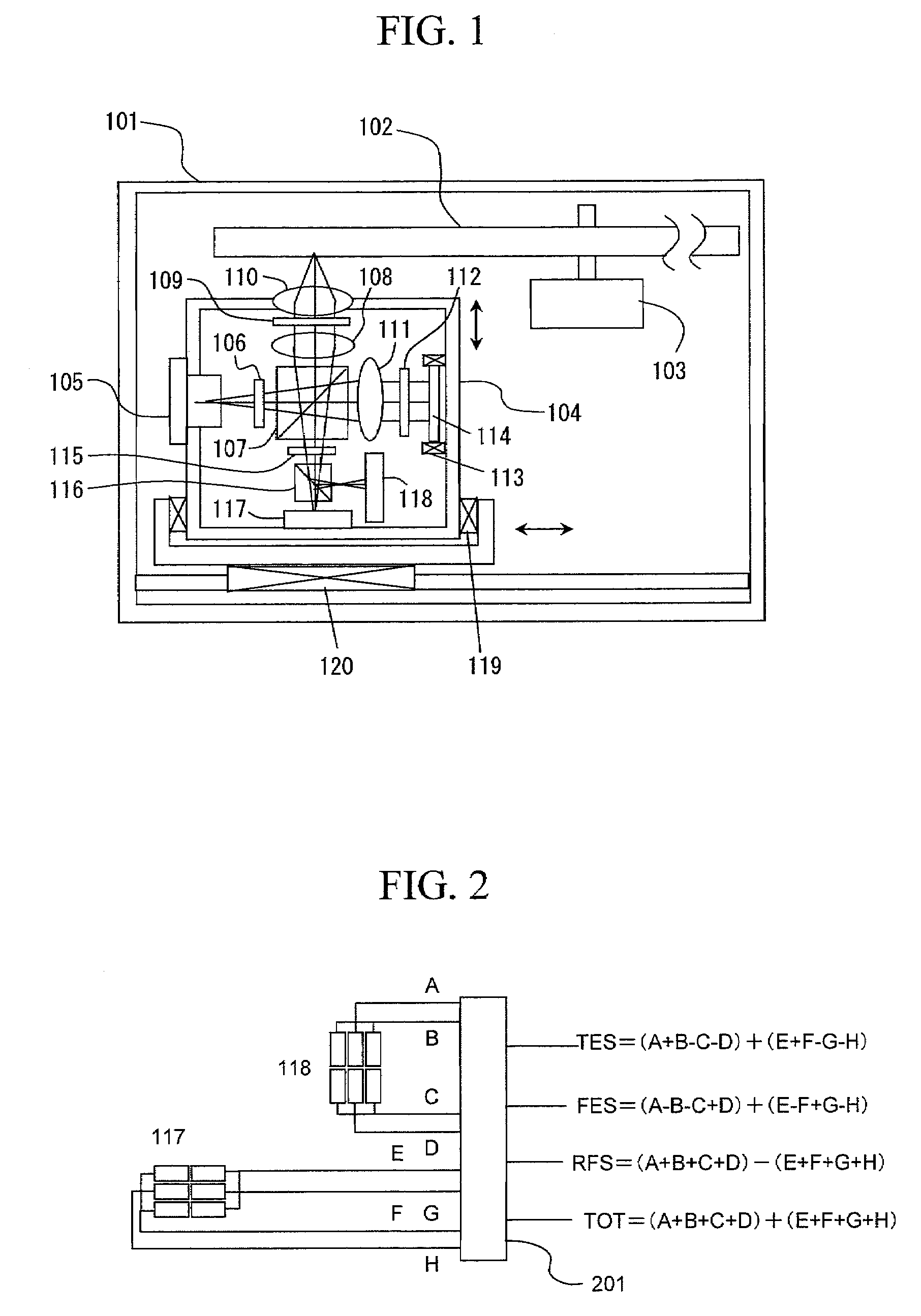
[0024]In FIG. 1, an optical disk 102, a spindle motor 103 and an optical head unit 104 which records and reproduces information on and from the optical disk 102 are provided in a case 101 of an optical disc apparatus. The optical head unit 104 can be moved in an optical axis direction for focusing light onto the optical disk and in a radial direction of the disk by a focusing actuator 119 and a tracking actuator 120, respectively. In the optical head unit 104, a laser diode 105 is provided, and the emitted light therefrom has its polarization direction rotated by a half wave plate 106, and is made incident on a polarizing beam splitter 107. In the polarizing beam splitter 107, the S-polarization component is reflected, and the P-polarization component is transmitted. The reflected S-polarization component is set to be parallel light by a collimator lens 108, is co...

embodiment 3

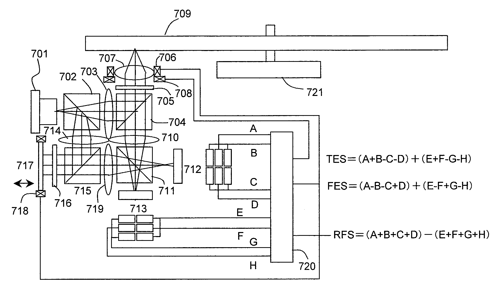
[0049]With reference to FIG. 7, Embodiment 3 of the present invention will be described. In this embodiment, not the Twyman-Green type but the Mach-Zehnder type optical system is used. Light emitted from a laser diode 701 is divided into two lights by a non-polarizing beam splitter 702. One of the lights is transmitted toward an optical disk 709, and the other light is reflected toward a reference mirror 717. A ratio of division of the light by the non-polarizing beam splitter 702 is not limited to 1:1. The amount of light traveling toward the reference mirror is set larger for signal amplification. The light traveling toward the optical disk 709 is set to be parallel light by a collimator lens 703, is reflected by a polarizing beam splitter 704, is converted into circular polarization by a quarter wave plate 705, and is focused on the optical disk 709 by an objective lens 707 which is mounted on a focusing actuator 706 and a tracking actuator 708. The reflected light is returned to...

embodiment 5

[0055]With reference to FIG. 9, Embodiment 5 of the present invention will be described. A laser diode chip 901 is placed on a SiC sub-mount 902 mounted on a silicon substrate 903. Light from the laser diode chip is separated into two lights by a first separation surface of a compound prism 904. One of the lights travels toward an optical disk 909 and the other travels toward a reference mirror 914. The first separation surface of the compound prism is a non-polarizing beam splitter. Moreover, as to a separation ratio of the lights, an amount of the light traveling toward the reference mirror 914 is set larger. The light traveling toward the optical disk 909 is reflected by a second separation surface corresponding to a polarizing beam splitter, and is transmitted through a quarter wave plate 905. The transmitted light is set to be parallel light by a collimator lens 906 and is focused on the optical disk by an objective lens 907. The quarter wave plate 905, the collimator lens 906 ...


PUM

PropertyMeasurementUnit
frequencyaaaaaaaaaa
optical path lengthaaaaaaaaaa
lengthaaaaaaaaaa

Abstract

Provided is an optical disc apparatus including an interference-type optical disk signal detection system, which allows an optical path difference between two kinds of light to be controlled easily, which has a high signal amplification effect, and which is suitable for miniaturization of an optical system. An interference-type optical system is integrally formed to stabilize an optical path difference between signal light and reference light. At the same time, means for controlling an optical path length of the reference light is attached to a reference mirror, and thereby controls signal amplitude so as to be constantly set the maximum in response to a change in the optical path length with time due to a variation in the thickness of a cover layer of an optical disk, a temperature and the like. Moreover, the optical system is miniaturized by using a Twyman-Green type interference optical system.

Description

CLAIM OF PRIORITY[0001]The present application claims priority from Japanese application JP 2006-144744 filed on May 25, 2006, the content of which is hereby incorporated by reference into this application.BACKGROUND OF THE INVENTION[0002]1. Field of the Invention[0003]The present invention relates to a higher signal-to-noise ratio of a read-out signal in an optical disc apparatus.[0004]2. Description of the Prior Art[0005]As to optical discs, a Blu-ray Disc which is read and written by using a blue laser diode and a high NA (Numerical Aperture) objective lens has been commercialized. With this commercialization, it is considered that the optical discs have almost reached its limit in terms of the resolution of its optical system, and that, hereafter, a multi-layer structure in an optical disc is effective in order to further achieve a larger capacity in the optical disc. In a multi-layer optical disc, the amounts of light detected from respective layers need to be approximately the...

Claims


Application Information

Patent Timeline
Patent Type & Authority Patents(United States)
IPC IPC(8): G11B7/00
CPCG11B7/1356G11B7/1365G11B7/1362G11B7/09G11B7/135
Inventor SHIMANO, TAKESHIMIYAMOTO, HARUKAZU
Owner HITACHI LTD
Why Eureka
Try Eureka