Optical disk apparatus
- Summary
- Abstract
- Description
- Claims
- Application Information
AI Technical Summary
Benefits of technology
Problems solved by technology
Method used
Image
Examples
embodiment 1
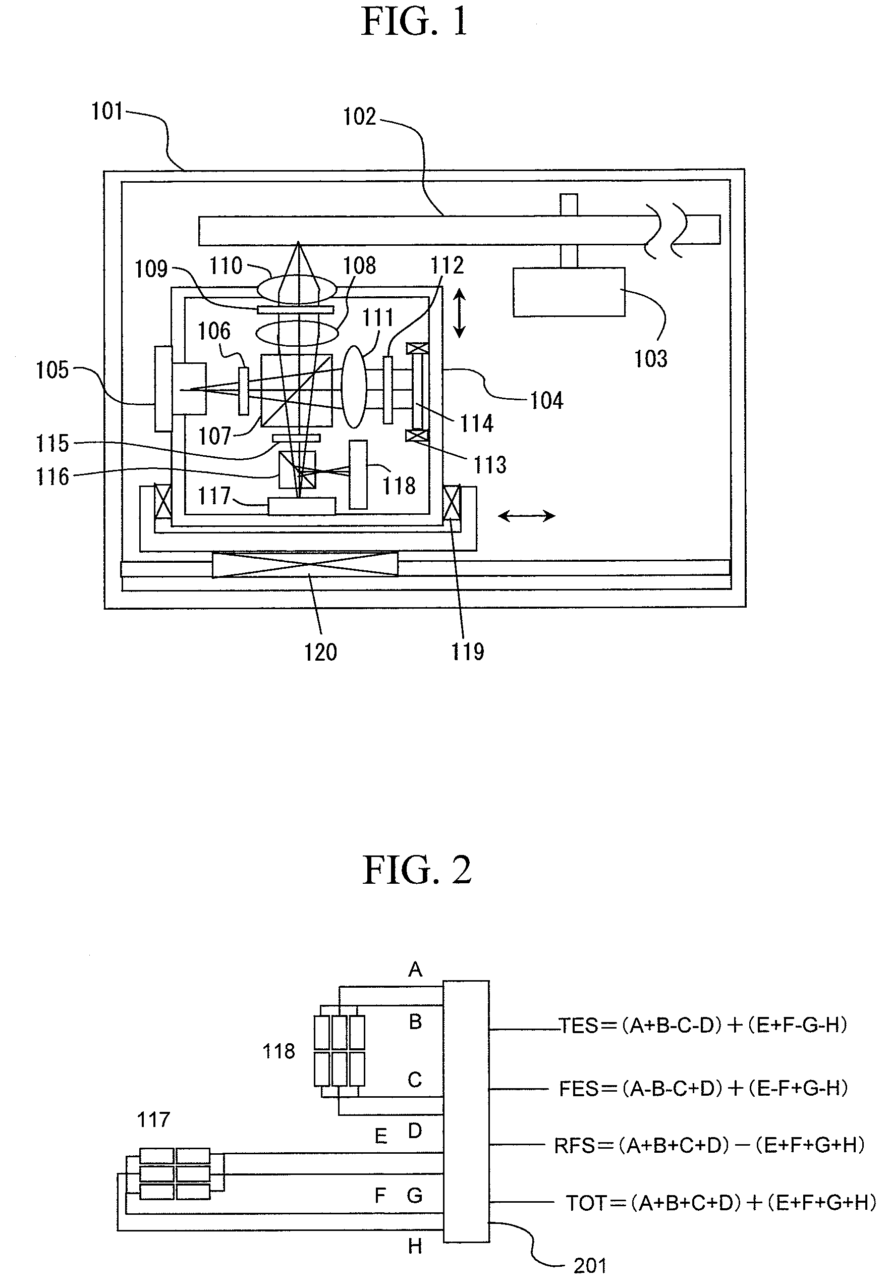
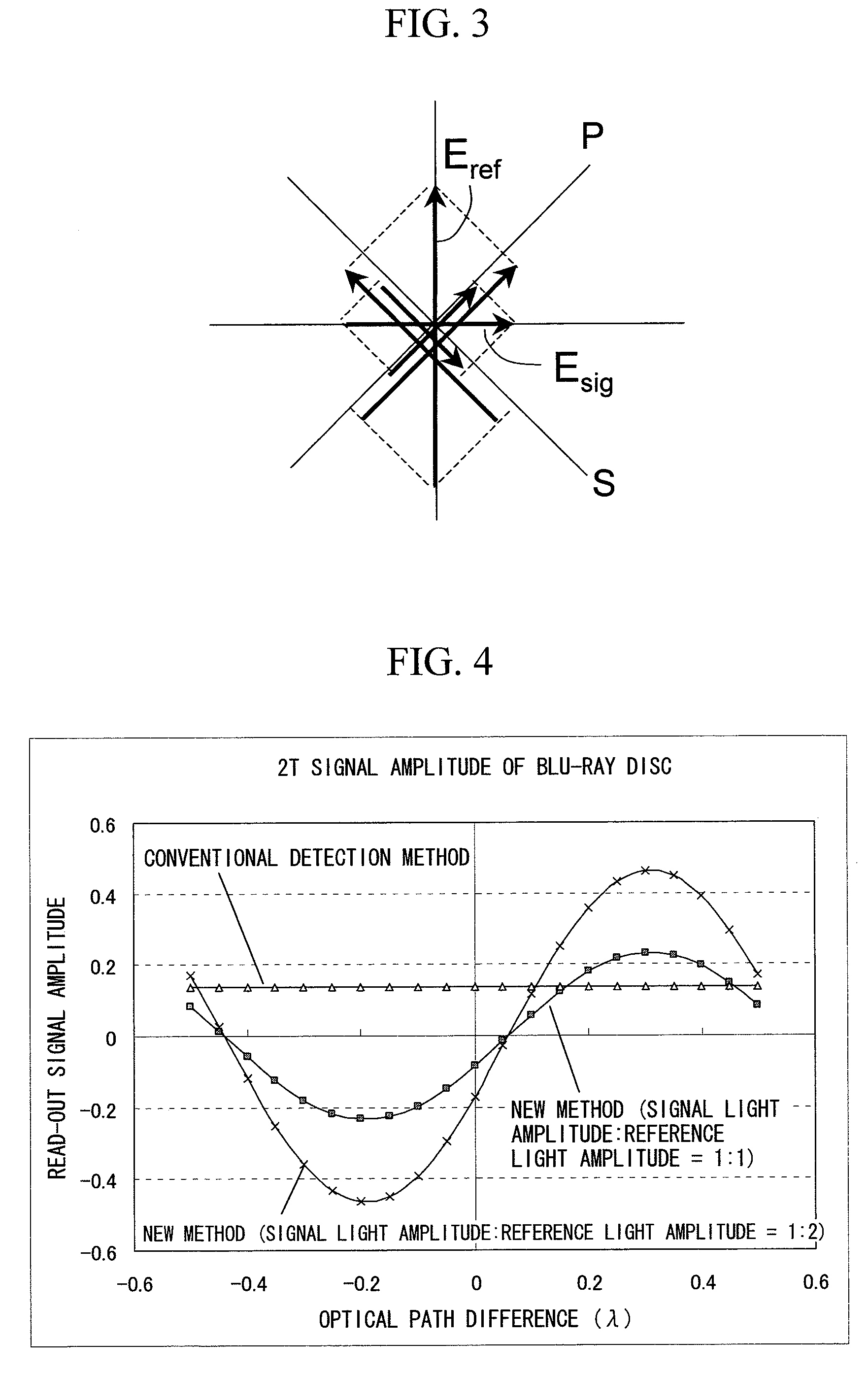
[0023]With reference to FIGS. 1 to 5, Embodiment 1 that is a basic embodiment of the present invention will be described.
[0024]In FIG. 1, an optical disk 102, a spindle motor 103 and an optical head unit 104 which records and reproduces information on and from the optical disk 102 are provided in a case 101 of an optical disc apparatus. The optical head unit 104 can be moved in an optical axis direction for focusing light onto the optical disk and in a radial direction of the disk by a focusing actuator 119 and a tracking actuator 120, respectively. In the optical head unit 104, a laser diode 105 is provided, and the emitted light therefrom has its polarization direction rotated by a half wave plate 106, and is made incident on a polarizing beam splitter 107. In the polarizing beam splitter 107, the S-polarization component is reflected, and the P-polarization component is transmitted. The reflected S-polarization component is set to be parallel light by a collimator lens 108, is co...
embodiment 3
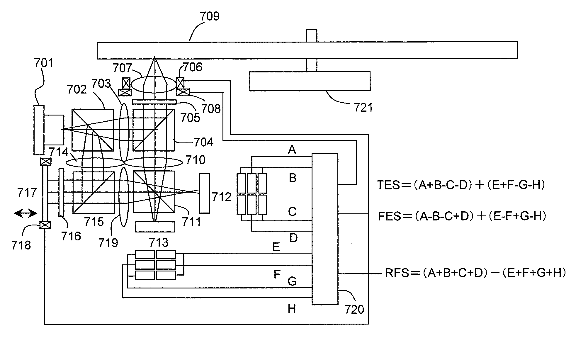
[0042]With reference to FIG. 7, Embodiment 3 of the present invention will be described. In this embodiment, not the Twyman-Green type but the Mach-Zehnder type optical system is used. Light emitted from a laser diode 701 is divided into two lights by a non-polarizing beam splitter 702. One of the lights is transmitted toward an optical disk 709, and the other light is reflected toward a reference mirror 717. A ratio of division of the light by the non-polarizing beam splitter 702 is not limited to 1:1. The amount of light traveling toward the reference mirror is set larger for signal amplification. The light traveling toward the optical disk 709 is set to be parallel light by a collimator lens 703, is reflected by a polarizing beam splitter 704, is converted into circular polarization by a quarter wave plate 705, and is focused on the optical disk 709 by an objective lens 707 which is mounted on a focusing actuator 706 and a tracking actuator 708. The reflected light is returned to...
embodiment 5
[0048]With reference to FIG. 9, Embodiment 5 of the present invention will be described. A laser diode chip 901 is placed on a SiC sub-mount 902 mounted on a silicon substrate 903. Light from the laser diode chip is separated into two lights by a first separation surface of a compound prism 904. One of the lights travels toward an optical disk 909 and the other travels toward a reference mirror 914. The first separation surface of the compound prism is a non-polarizing beam splitter. Moreover, as to a separation ratio of the lights, an amount of the light traveling toward the reference mirror 914 is set larger. The light traveling toward the optical disk 909 is reflected by a second separation surface corresponding to a polarizing beam splitter, and is transmitted through a quarter wave plate 905. The transmitted light is set to be parallel light by a collimator lens 906 and is focused on the optical disk by an objective lens 907. The quarter wave plate 905, the collimator lens 906 ...
PUM
 Abstract
Description
Claims
Application Information
 - R&D
- Intellectual Property
- Life Sciences
- Materials
- Tech Scout
- Unparalleled Data Quality
- Higher Quality Content
- 60% Fewer Hallucinations
Browse by: Latest US Patents, China's latest patents, Technical Efficacy Thesaurus, Application Domain, Technology Topic, Popular Technical Reports.
© 2025 PatSnap. All rights reserved.Legal|Privacy policy|Modern Slavery Act Transparency Statement|Sitemap|About US| Contact US: help@patsnap.com


