
Tunable support frame structure for rotating machines

a technology for rotating machines and support frames, which is applied in the direction of machine supports, machine frames, special foundation layouts, etc., can solve the problems of consuming a considerable amount of research time, and achieve the effects of enhancing the directional stiffness of the mounting assembly, preventing the rigid body mode of the machine, and increasing the stiffness

Active Publication Date: 2019-05-14
BHATTACHARYA MANTOSH ISANCHANDRA
View PDF14 Cites 1 Cited by
  • Summary
  • Abstract
  • Description
  • Claims
  • Application Information

AI Technical Summary

Benefits of technology

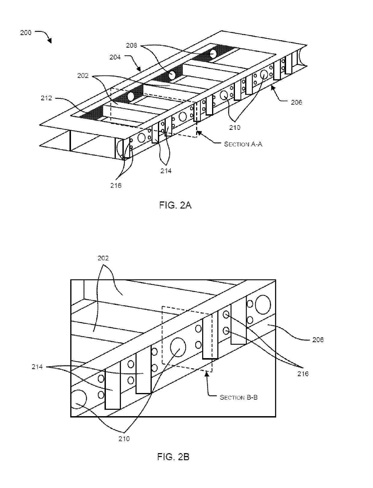
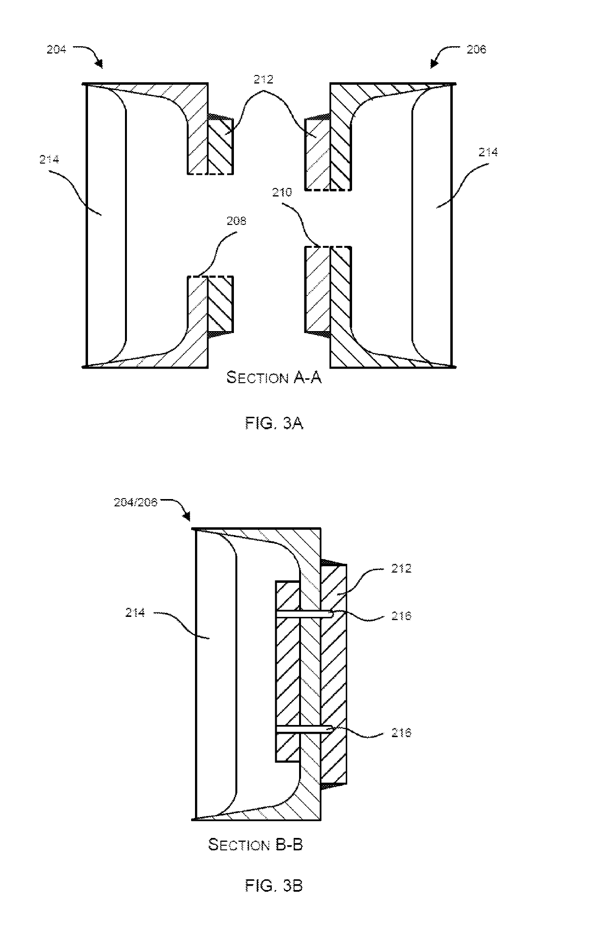
The present disclosure provides a mounting assembly for supporting a rotating machine to prevent rigid body modes of the machine. The mounting assembly includes a support frame structure with increased stiffness in a specific direction to prevent rigid body modes of the machine. The assembly also includes an attachment mechanism to increase effective stiffness of the support frame structure. The attachment mechanism may include a plurality of attachments, a turnbuckle attachment, or a combination of both. The attachment mechanism removes any or a combination of rolling mode of motion and pitching mode of motion of the support frame structure and the machine. The turnbuckle attachment provides stability and support to an overhung component of the machine. The mounting assembly is designed to prevent machine vibration and improve machine performance.

Problems solved by technology

Currently used investigation techniques for determining possibility of structural resonance of the mounting assembly excited by forcing operating frequency of a rotating machine are lengthy and intricate processes, and utilize analytical techniques such as bump test, finite element analysis, experimental modal analysis, operational deflection shape analysis, mode shapes plotting, etc.
Such investigation techniques take a considerable amount of time particularly if the machines are installed at a remote location.

Method used


Image

  • Tunable support frame structure for rotating machines
  • Tunable support frame structure for rotating machines
  • Tunable support frame structure for rotating machines

Examples


Embodiment Construction

[0039]If the specification states a component or feature “may”, “can”, “could”, or “might” be included or have a characteristic, that particular component or feature is not required to be included or have the characteristic.

[0040]Exemplary embodiments will now be described more fully hereinafter with reference to the accompanying drawings, in which exemplary embodiments are shown. This disclosure may however, be embodied in many different forms and should not be construed as limited to the embodiments set forth herein. These embodiments are provided so that this disclosure will be thorough and complete and will fully convey the scope of the disclosure to those of ordinary skill in the art. Moreover, all statements herein reciting embodiments of the disclosure, as well as specific examples thereof, are intended to encompass both structural and functional equivalents thereof. Additionally, it is intended that such equivalents include both currently known equivalents as well as equival...


PUM


Abstract

The present disclosure relates to a mounting assembly for supporting a machine. The mounting assembly comprises a support frame structure including a plurality of traverse members spaced apart from each other, each traverse member extending from a first longitudinal section to a second longitudinal section of the support frame structure, wherein each longitudinal sections and comprises a plurality of holes and respectively, and an attachment mechanism to increase effective stiffness of the support frame structure, the attachment mechanism comprising any or a combination of a plurality of attachments and a turnbuckle attachment to increase directional stiffness of the support frame structure, wherein the attachment mechanism arrests any or a combination of rolling mode of motion and pitching mode of motion of the support frame structure and the machine by increasing the effective stiffness of the support frame structure.

Description

TECHNICAL FIELD[0001]The present invention relates generally to mounting assemblies of machineries, and more particularly to a mounting assembly for supporting a rotating machine to prevent rigid body modes, particularly rotational rigid body modes of the machine.BACKGROUND OF THE INVENTION[0002]Background description includes information that may be useful in understanding the present invention. It is not an admission that any of the information provided herein is prior art or relevant to the presently claimed invention, or that any publication specifically or implicitly referenced is prior art.[0003]Many rotating machines, such as motors, pumps, fans and the like, are connected to suitable ground supports via mounting assemblies. Such mounting assemblies are intended to absorb vibrations, but must also be capable of supporting weight of the machines and its dynamic forces during operation without getting excited at operating / forcing frequencies thereof (for example, due to variati...

Claims


Application Information

Patent Timeline
Patent Type & Authority Patents(United States)
IPC IPC(8): F16M5/00F16M7/00
CPCF16M7/00F16M5/00F16M1/08F16M9/00
Inventor BHATTACHARYA, MANTOSH ISANCHANDRA
Owner BHATTACHARYA MANTOSH ISANCHANDRA
Learn More