
Dip tube

a technology of dip tubes and spherical tubes, which is applied in the direction of indirect heat exchangers, lighting and heating apparatus, heat storage plants, etc., can solve the problems of clogging, rusting and eventually leakage, and the introduction of brass to steel water heaters that are not dielectrically correct connections, etc., and achieves the effect of maximizing slowness

Active Publication Date: 2019-05-14
MERCURY PLASTICS LLC
View PDF34 Cites 8 Cited by
  • Summary
  • Abstract
  • Description
  • Claims
  • Application Information

AI Technical Summary

Benefits of technology

The patent describes a need to simplify the installation and repair of a dip tube for a water heater, as well as reducing the cost and preventing leaks. The invention achieves this by integrating the dip tube with the pipe nipple and minimizing the material between the openings to slow down the flow of water and provide structural support during use. This results in lower labor and materials costs for the manufacturer and servicemen, and also minimizes the risk of leaks.

Problems solved by technology

Although the exterior of galvanized nipples are dielectrically compatible with the steel water heater, the interior of the galvanized nipple is not.
With the interior unprotected, the galvanized nipple corrodes, clogs, rusts and eventually leaks.
Brass nipples, on the other hand, internally will not corrode like galvanized nipples, but the introduction of brass to the steel water heater is not a dielectrically correct connection.
Left unprotected, the area of the steel water heater below the brass nipple corrodes.
This results in increased amounts of labor for verification of both the proper assembly and efficient functionality of each separate component.
This increased labor results in increased costs for the manufacturer and servicemen which are typically passed on to the consumer.
Moreover, improper installation of these separate components can result in leaks, which may form between the dip tube and the pipe nipple.
The drilling or punching of the holes may not be dimensionally accurate due to the inaccuracy of the tools used for drilling or punching as well as operator error.
This dimensional inaccuracy of the holes creates uneven dispersion of the cold water at the bottom of the water heater which increases the mixture of cold water with the hot water in the water heater and increases heat loss.
The heat sealing process creates inconsistent results and requires an expensive piece of equipment.
The extensive labor involved in drilling or punching the holes and subsequent melting of the bottom of dip tube increases the overall costs associated with the dip tube.

Method used


Image

  • Dip tube
  • Dip tube
  • Dip tube

Examples


Embodiment Construction

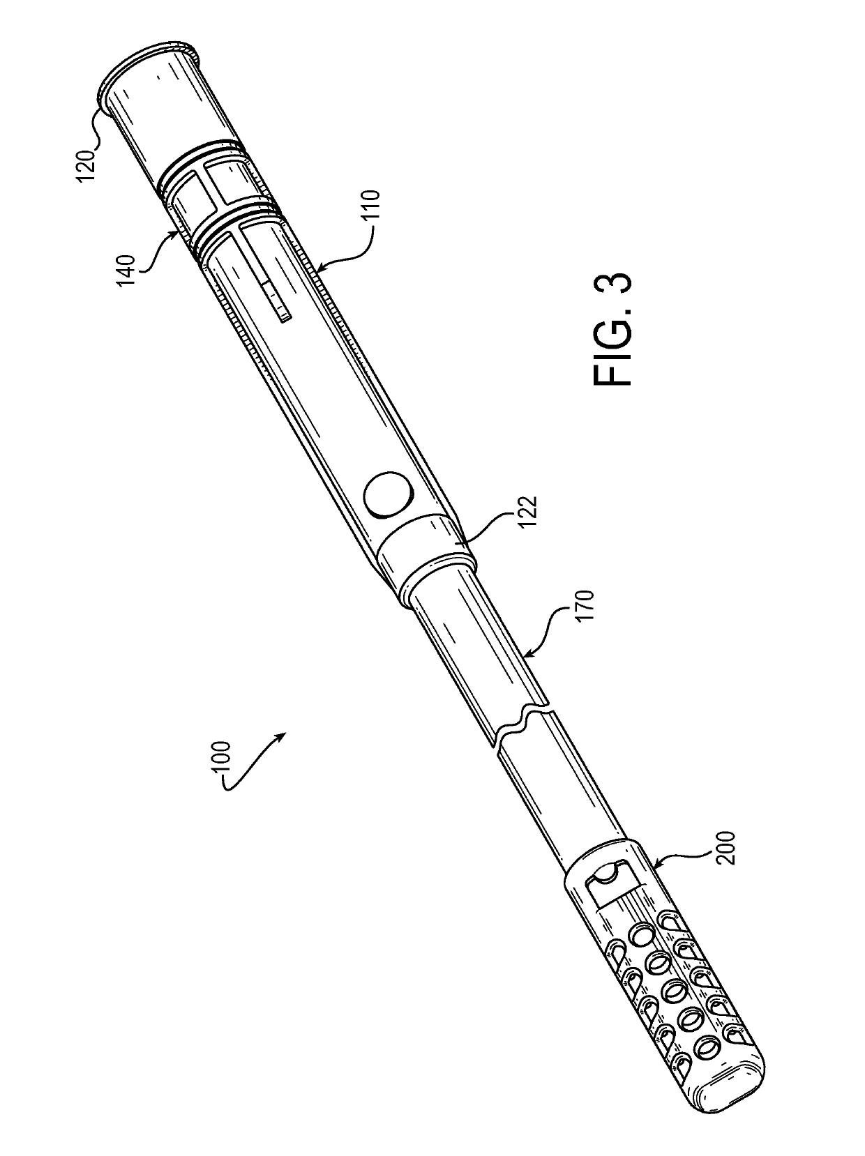
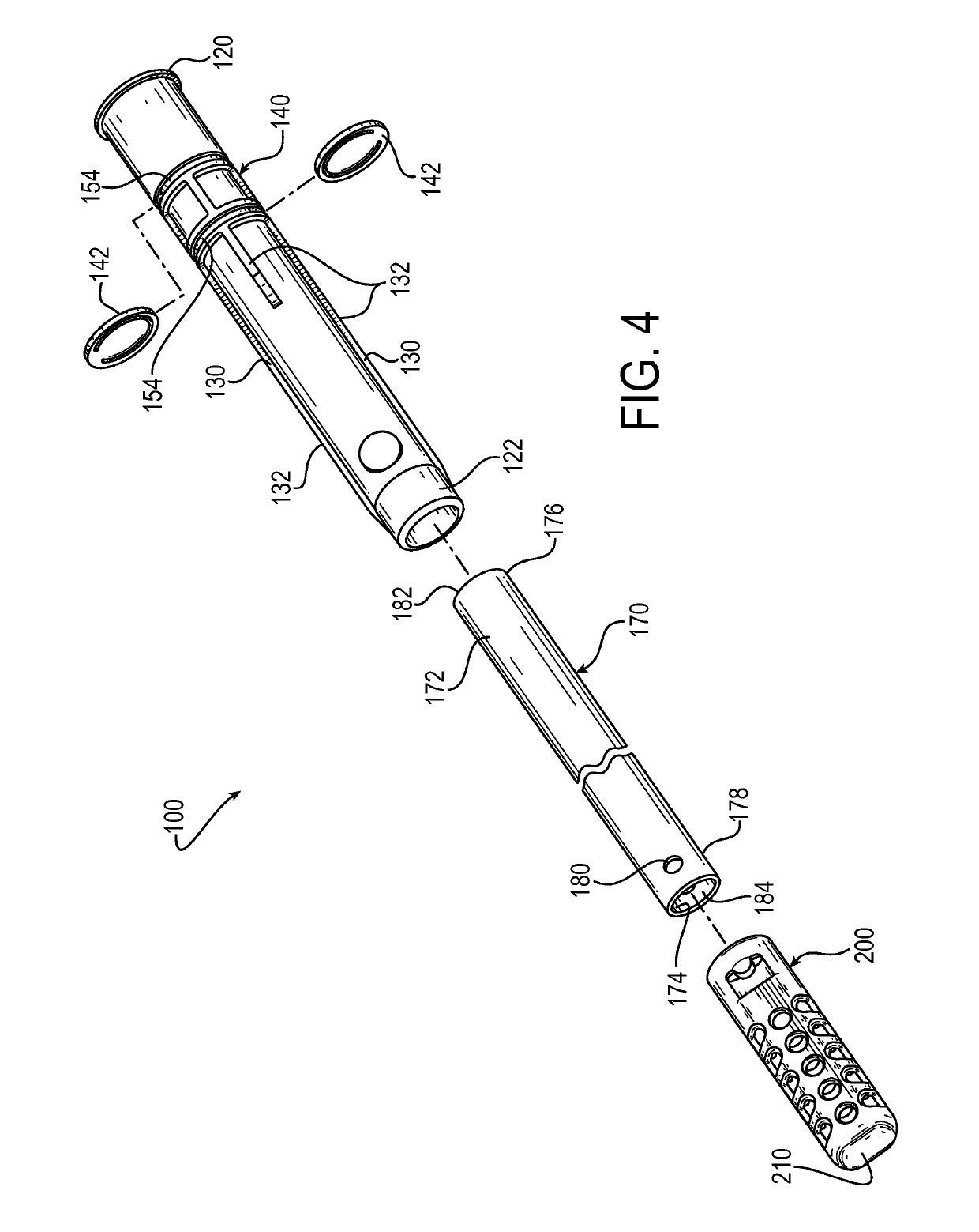
[0052]Various embodiments of the invention described herein provide a leak free dip tube that replaces multiple separate components including a dielectric liner, heat trap assemblies, a gasket and a dip tube cup or retaining cup for a water heater. The leak free dip tube may be a one-piece construction.

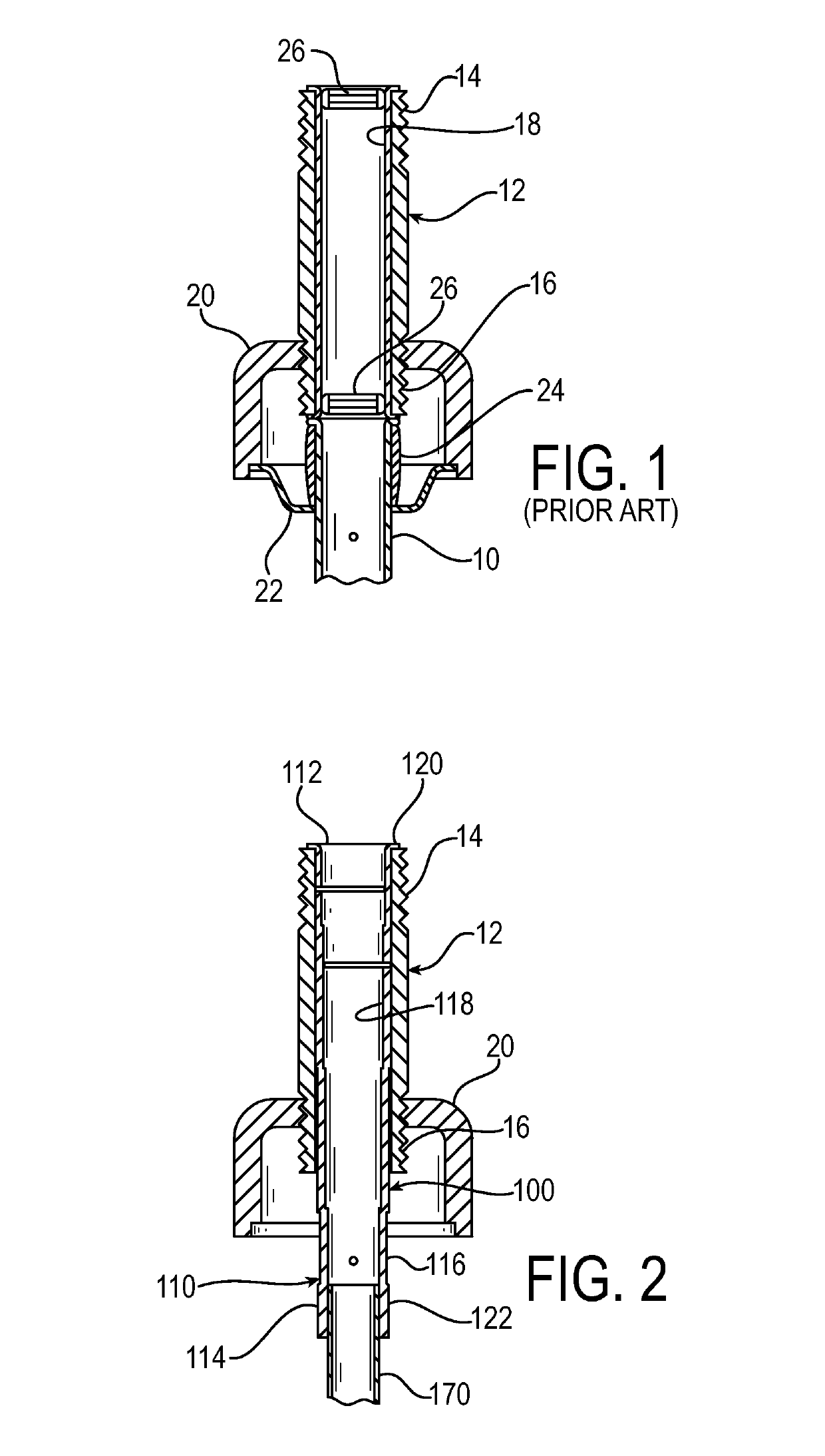
[0053]As noted above, there are a number of separate components with respect to installation, repair and replacement a dip tube for a water heater. By example, FIG. 1 displays a cross-sectional view of a dip tube 10 connected to a nipple 12 of a water heater according to the prior art. Nipple 12 includes upper threads 14 and lower threads 16 on each end of the nipple 12. A dielectric liner 18 is located on the inner surface of the nipple 12. Upper thread 14 connects to plumbing (not shown) while lower thread 16 connects to a coupling 20 of the water heater. A dip tube cup or retaining cup 22 is located near the bottom of the coupling 20. A gasket 24 is located below the nipple 12 and ...


PUM


Abstract

A dip tube for use with a water heater having a pipe nipple, the dip tube including an upper end and a tubular body, where the upper end is located above the tubular body. The upper end has an outer wall, a top portion and bottom portion, and further includes a flange located at the top portion. The flange extends outwardly from the outer wall to retain the dip tube at the pipe nipple. The upper end also includes a reinforced connecting portion located at the bottom portion for connecting the upper end to the tubular body, where a portion of the tubular body is located within the reinforced connecting portion.

Description

[0001]This application claims the benefit of U.S. Provisional Patent Application No. 61 / 859,575, filed Jul. 29, 2013 and U.S. Provisional Patent Application No. 61 / 915,782, filed Dec. 13, 2013.BACKGROUND AND SUMMARY OF THE INVENTION[0002]It is known to provide a dip tube in a water heater to supply cold water to the tank. The cold water is injected at the bottom of the tank through the dip tube. The cold water is then heated where it rises in the water heater and is drawn off by a hot water discharge pipe. A pipe nipple connects to the water heater, the water heater being made from steel, and allows plumbing for the cold water inlet to be connected to the water heater. The pipe nipple is threaded on both ends and is typically made of brass, galvanized steel, or galvanized steel with a dielectric insert.[0003]Although the exterior of galvanized nipples are dielectrically compatible with the steel water heater, the interior of the galvanized nipple is not. With the interior unprotecte...

Claims


Application Information

Patent Timeline
IPC IPC(8): F24H9/00F24H9/14
CPCF24H9/0047F24H9/14F24H9/0015F28D2020/0069F24H9/45F24H9/133F24H9/455
Inventor CURREY, DONALDGARDNER, SCOTT R.
Owner MERCURY PLASTICS LLC
Learn More