
Low cost high efficiency solar power plant

a solar power plant and high efficiency technology, applied in solar heat collectors, lighting and heating equipment, greenhouse gas reduction, etc., can solve the problems of not even remotely acceptable, economic unpractical, and large difference in energy available in summers as compared to winters, and achieve simple and cost-effective structure, efficient and cheap heat storage units, and simple and cost-effective

Active Publication Date: 2019-05-14
VERMA SUBODH
View PDF19 Cites 0 Cited by
  • Summary
  • Abstract
  • Description
  • Claims
  • Application Information

AI Technical Summary

Benefits of technology

The invention is a system and plant that can protect dishes from wind with a simple and cost-effective arrangement. The technical effects are improved protection of dishes and reduced wind damage to the system and plant.

Problems solved by technology

Since solar plants will always be set up in deserts where the environment is very dusty and has high wind speeds due to the flat open landscape, any successful design will have to be unaffected by these conditions.
At present, most of existing solar plants have been designed with storage units which can provide only a few hours of backup, which is not even remotely acceptable.
Another technical challenge that solar power plants will face will be the great difference in energy that is available in summers as compared to winters.
However, the odds are that most of the cities would be much farther away from the solar power plant and would, therefore, have to use electricity for heating and cooking purposes.
This is economically not practical.

Method used


Image

  • Low cost high efficiency solar power plant
  • Low cost high efficiency solar power plant
  • Low cost high efficiency solar power plant

Examples


Embodiment Construction

[0112]The following description with reference to the accompanying drawings is provided to assist in a comprehensive understanding of exemplary embodiments of the invention as defined by the claims and their equivalents. It includes various specific details to assist in that understanding but these are to be regarded as merely exemplary.

[0113]Accordingly, those of ordinary skill in the art will recognize that various changes and modifications of the embodiments described herein can be made without departing from the scope and spirit of the invention. In addition, descriptions of well-known functions and constructions are omitted for clarity and conciseness.

[0114]The terms and words used in the following description and claims are not limited to the bibliographical meanings, but, are merely used by the inventor to enable a clear and consistent understanding of the invention. Accordingly, it should be apparent to those skilled in the art that the following description of exemplary emb...


PUM


Abstract

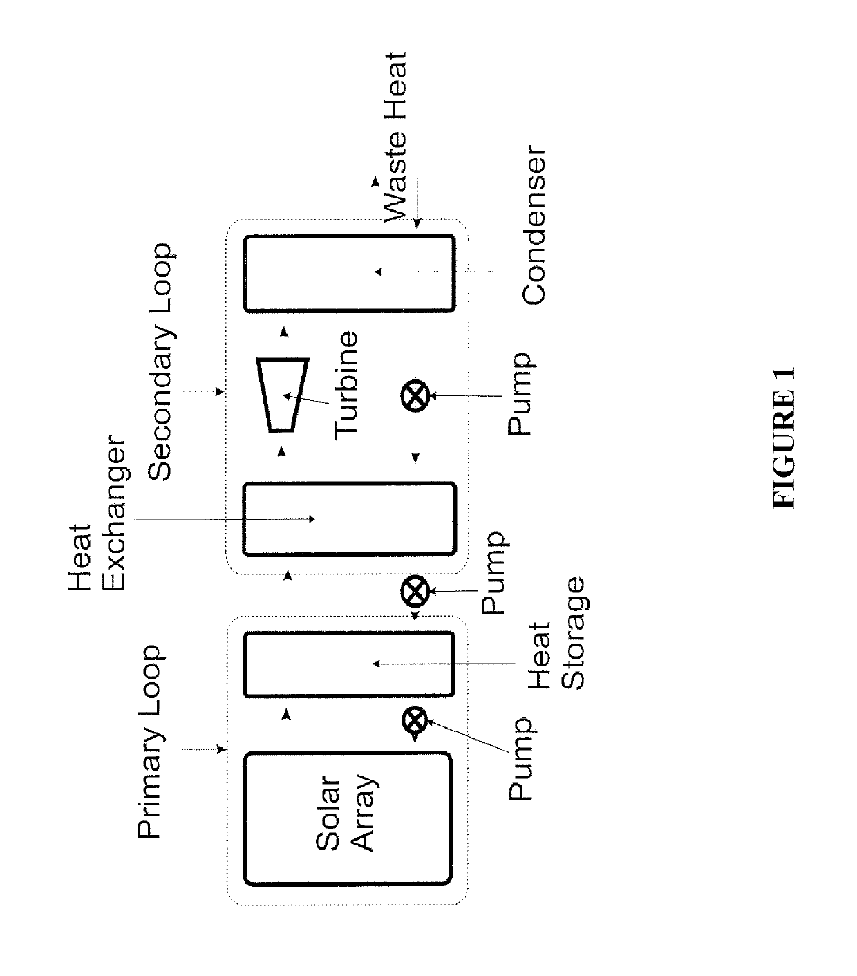
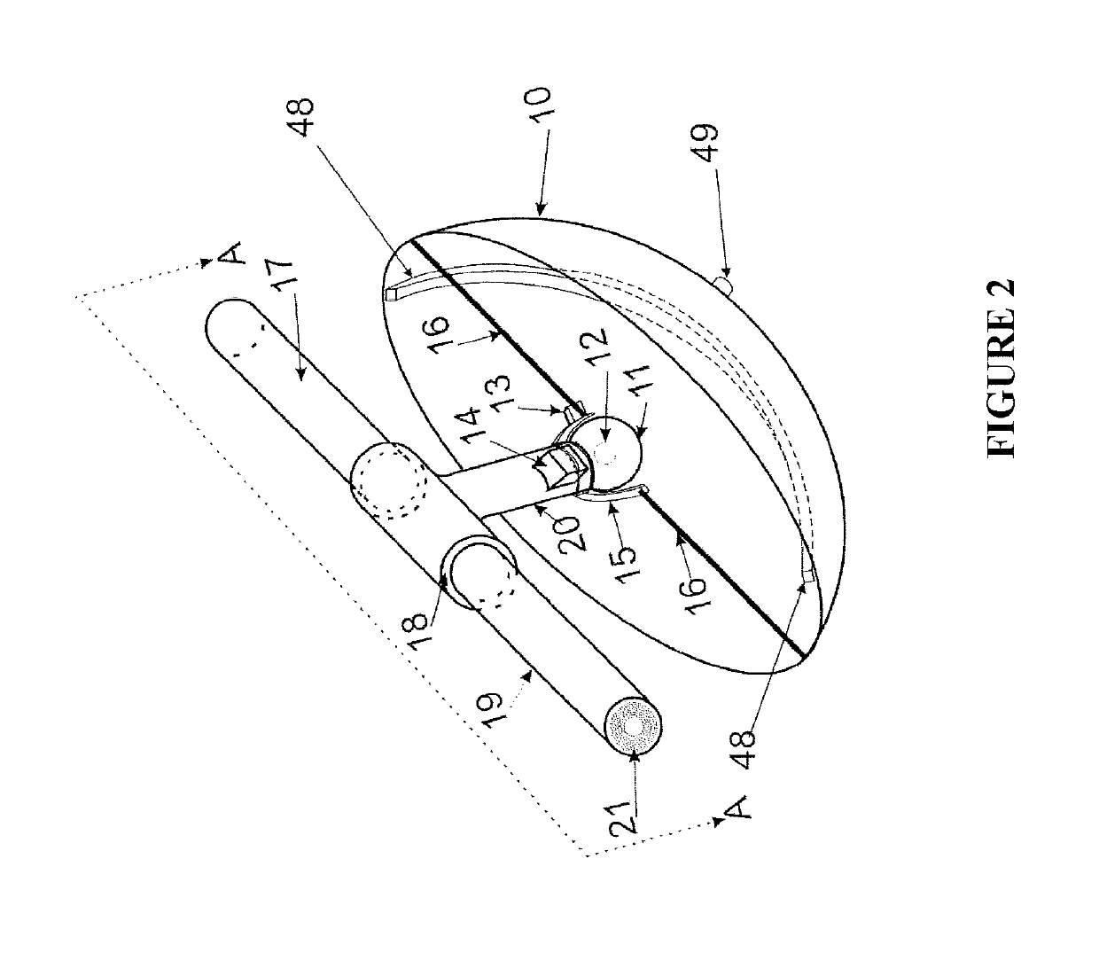
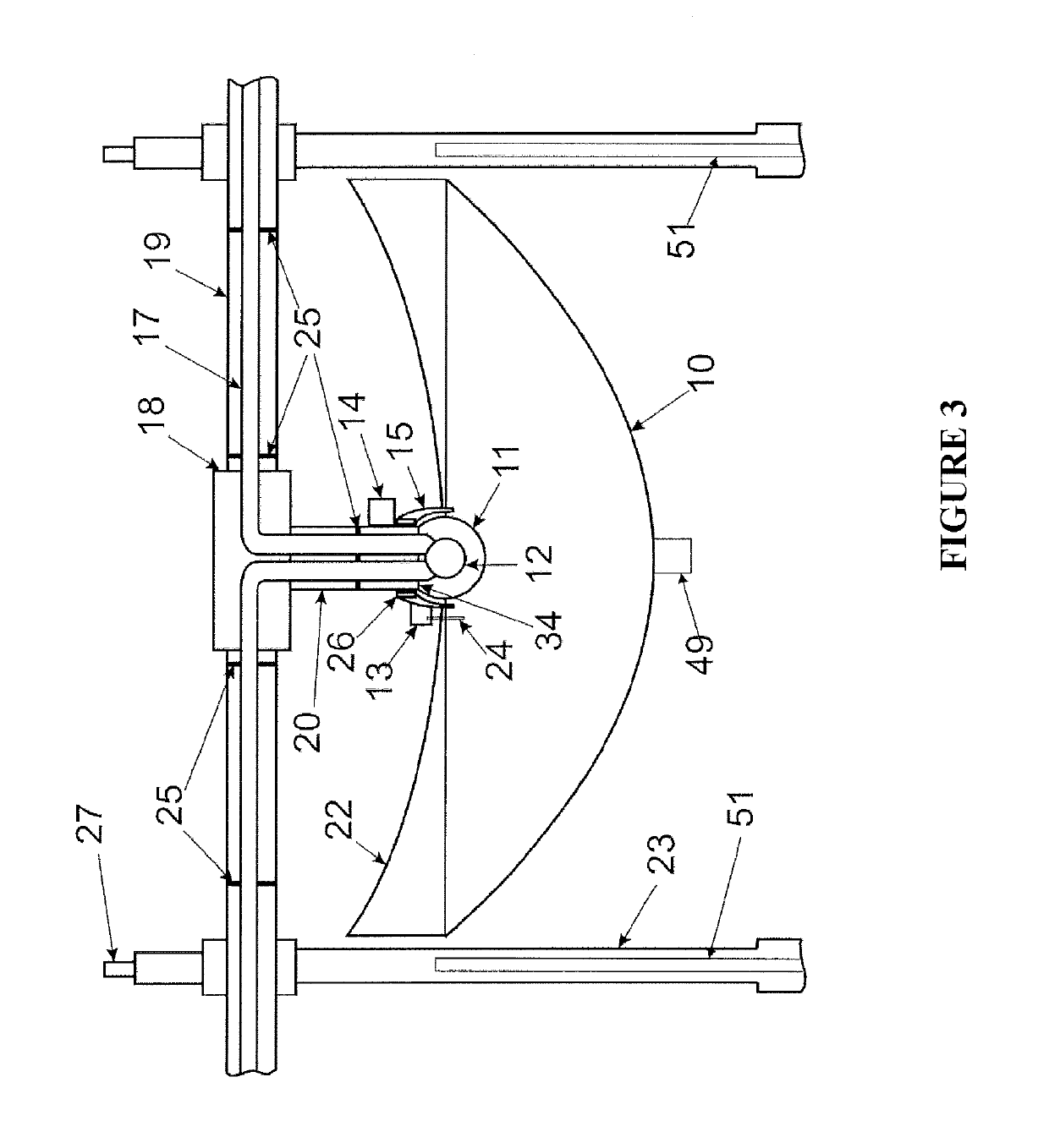
The present invention relates to a system and apparatus which is designed to use parabolic concentrator to focus sunlight onto a receiver which uses a coolant to carry the heat to the heat storage unit. The system comprises a primary loop comprising at least one solar array and at least one heat storage unit. The system further comprises a secondary loop operatively communicating with said primary loop. The solar array comprises plurality of reflector dish assemblies comprising reflector dish means whereby said dish means are arranged in close proximity to each other wherein said dish means being such that high sunlight concentration ratio is obtained for providing high conversion efficiency from heat to electricity.

Description

PRIORITY CLAIM[0001]This application is a continuation-in-part of International Application No. PCT / IB2013 / 058302 filed on Sep. 5, 2013, published as WO 2014 / 037892 on Mar. 13, 2014, and of Indian Patent Application No.: 2769 / DEL / 2012 filed on Sep. 6, 2012, which are all hereby incorporated by reference in their entirety.FIELD OF THE INVENTION[0002]The present invention relates to a very low cost yet high efficiency system and apparatus which is designed to use parabolic concentrator to focus sunlight onto a receiver which uses a coolant to carry the heat to the heat storage unit. A secondary loop using water as the coolant draws heat from the heat storage unit and is used to run a turbine to generate electricity. The waste heat from the secondary loop can further be used to run a desalination plant, or simply lost to the environment.BACKGROUND OF THE INVENTION[0003]Currently there are several systems which have been developed or are under development for converting sunlight into el...

Claims


Application Information

Patent Timeline
Patent Type & Authority Patents(United States)
IPC IPC(8): F03G6/06F24S10/70F24S23/70F24S10/00F24S50/20F28D20/00F24S40/20F24S23/71F24S80/60F24S80/30F24S40/50F24S80/50F24S20/20F24S40/40F24S25/12F24S30/45F24S10/40F24S90/00
CPCF24S50/20F24S10/00F24S10/70F24S20/20F24S23/70F24S23/71F24S23/82F24S25/12F24S30/45F24S40/20F24S40/40F24S40/50F24S80/30F24S80/50F24S80/60F28D20/0056F03G6/067Y02E70/30Y02A40/227Y02E10/41Y02E10/42Y02E10/46Y02E10/47Y02E60/142Y02A40/22Y02E10/40Y02E60/14Y02E10/44
Inventor VERMA, SUBODH
Owner VERMA SUBODH
Learn More