Relocating data from an end of life storage drive based on storage drive loads in a data storage system using mapped RAID (redundant array of independent disks) technology

a data storage system and end of life technology, applied in the field of intelligent data storage systems, can solve the problems of the amount of time required to rebuild data, the inability to add new disks, and the significant limitations of the data storage system providing traditional raid data protection, so as to reduce the risk of performance bottlenecks, reduce overall copy time, and improve copy performance

Active Publication Date: 2019-05-14
EMC IP HLDG CO LLC
View PDF11 Cites 10 Cited by
  • Summary
  • Abstract
  • Description
  • Claims
  • Application Information

AI Technical Summary

Benefits of technology

[0011]The mapped RAID technology described herein improves on traditional RAID technology by allowing for the addition of individual non-volatile data storage drives to a data storage system in order to increase the storage capacity of the system, and also addresses the problem of long rebuild times in traditional RAID caused by write bandwidth bottlenecks when writing to dedicated spare disks. In the mapped RAID technology described herein, each storage drive is divided into multiple contiguous regions of non-volatile data storage referred to as “drive extents”. A drive extent pool is generated from the drive extents. The drive extent pool maintains indications of the drive extents, as well as indications of whether each individual drive extent has been allocated or is available for allocation. A RAID extent table is generated that contains multiple RAID extent entries, each one of which indicates a unique set of drive extents that have been allocated from the drive extent pool to that RAID extent entry. The set of drive extents indicated by each RAID extent entry are used to store host data that is written to a corresponding portion of a logical address space representing the non-volatile storage accessed through the RAID mapping table and associated parity data, e.g. to store the host data written to a corresponding portion of the logical address space of a logical storage object representing the non-volatile storage accessed through the RAID mapping table and associated parity data. Each one of the drive extents allocated to any individual RAID extent must be located on a different storage drive. The drive extents indicated by a RAID extent entry are used to store the blocks of data and the associated parity information for a stripe of non-volatile data storage represented by that RAID extent entry. The total number of drive extents indicated by each RAID extent entry in the RAID extent table may be the same as the number of disks used in a traditional RAID system to store data blocks and parity information for the same RAID level. For example, in a mapped RAID system supporting a 4D+1P RAID-5 configuration, each RAID extent entry in the RAID extent table indicates a total of five drive extents, four of which are used to store the four blocks of host data, and one of which is used to store the parity information of the stripe represented by the RAID extent. In a 4D+2P RAID-6 mapped RAID configuration, two parity information blocks are indicated by each RAID extent entry to provide an increased level of fault tolerance, and each RAID extent entry in the RAID extent table indicates a total of six drive extents.
[0012]In the event that a drive enters an end of life state and must be replaced, in the mapped RAID technology described herein spare drive extents can be allocated from the drive extent pool that are located on multiple storage drives that contribute to the drive extent pool in order to replace drive extents located in the failed drive. In this way the disclosed mapped RAID technology may advantageously increase parallel processing while copying data from the end of life storage drive by spreading the necessary write operations across multiple healthy storage drives, thus effectively eliminating a write bandwidth bottleneck previously that may be caused by traditional RAID's reliance on copying to a single dedicated spare disk, and reducing the time required to respond to a single drive reaching an end of life state.
[0022]Embodiments of the technology described herein may provide significant advantages over previous technical solutions. For example, embodiments of the technology described herein copies data from drive extents located in an end of life source storage drive to corresponding destination drive extents evenly distributed across the remaining healthy storage drives in the group of storage drives. As a result, embodiments of the technology described herein reduce the risk of a performance bottleneck occurring because data from drive extents located in the source storage drive is predominantly copied to destination drive extents located in a small number of the remaining healthy storage drives. The technology described herein also advantageously selects optimal RAID extents located in the source storage drive to be added to the parallel copy list, based on the current total I / O loads of the healthy storage drives within the group of storage drives, which provides load balancing of I / O operations across the healthy storage drives. The technology described herein may determine a current total I / O load for each healthy storage drive in the group of storage drives that includes both host I / O load and background JO load, in order to reflect the actual I / O load each storage drive. The technology described herein takes advantage of the increased parallelism provided by mapped RAID technology, thus improving copy performance and reducing overall copy time. By reducing the overall amount of time required to relocate data stored on a storage drive from which an end of life indication has been received, embodiments of the technology described herein reduce the risk of losing data by reducing the risk that a second storage drive will fail during the copy process.

Problems solved by technology

Data storage systems providing traditional RAID data protection have had significant limitations with regard to the ability to add new disks, and with regard to the amount of time required to rebuild data in the event of a disk failure.
Specifically, traditional RAID systems do not support the addition of new disks on an individual disk basis, and instead require that new storage capacity be added only in numbers of disks equal to the number of disks that is required to support the specific RAID configuration, i.e. equal to the width of the RAID stripe being used.
As the capacity of individual disks has increased over time with the introduction of new storage technologies, this inflexibility in terms of adding new capacity to traditional RAID systems has become increasingly burdensome and impractical.
Also as individual disk capacity has increased, the time required by traditional RAID systems to rebuild data of an entire failed disk onto a single dedicated spare disk has increased, and the write bandwidth of the single dedicated spare disk has become a significant performance bottleneck with regard to a total rebuild time.
Moreover, while data previously stored on the failed disk is being rebuilt on the spare disk, concurrent failure of one or more additional disks in a traditional RAID system during the rebuilding process may introduce the risk of data loss.

Method used


Image

  • Relocating data from an end of life storage drive based on storage drive loads in a data storage system using mapped RAID (redundant array of independent disks) technology
  • Relocating data from an end of life storage drive based on storage drive loads in a data storage system using mapped RAID (redundant array of independent disks) technology
  • Relocating data from an end of life storage drive based on storage drive loads in a data storage system using mapped RAID (redundant array of independent disks) technology

Examples


Embodiment Construction

[0032]Embodiments of the invention will now be described. It should be understood that the embodiments described herein are provided only as examples, in order to illustrate various features and principles of the disclosed technology, and that the invention is broader than the specific embodiments described herein.

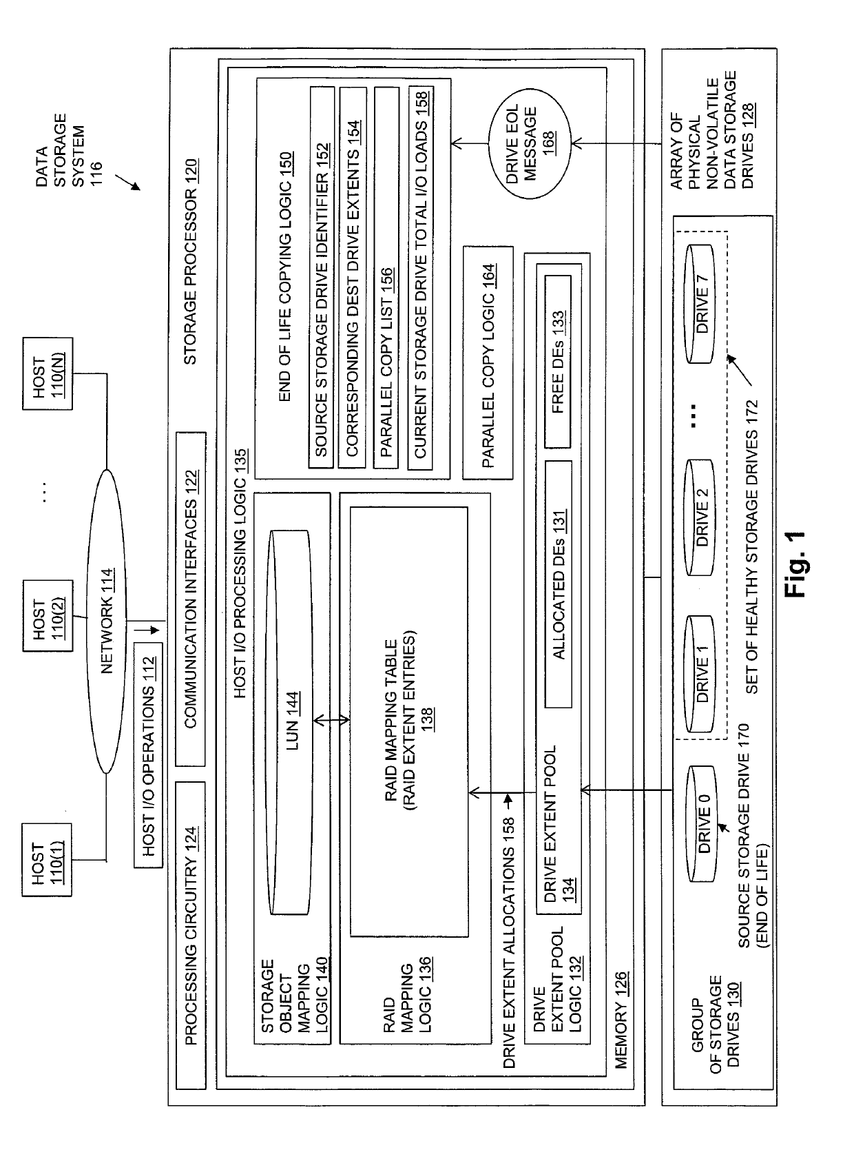
[0033]FIG. 1 is a block diagram showing an operational environment for the disclosed technology, including an example of a data storage system in which the disclosed technology may be embodied. The operational environment of FIG. 1 includes some number of Host Computing Devices 110, referred to as “hosts” and shown for purposes of illustration by Hosts 110(1) through 110(N), that access data storage provided by Data Storage System 116, for example over one or more computer networks, such as a local area network (LAN), and / or a wide area network (WAN) such as the Internet, etc., shown in FIG. 1 by Network 114. Data Storage System 116 includes at least one Storage Processor ...


PUM


Abstract

Technology for relocating data stored in an end of life source storage drive that identifies individual destination drive extents corresponding to drive extents located in the source storage drive by selecting individual storage drives within a set of healthy storage drives in a group of storage drives in a round robin manner and identifying an individual destination drive extent from each selected storage drive. The corresponding destination drive extents replace the drive extents located in the source storage drive, and are used to store data copied from the drive extents located in the source storage drive. Data is copied in parallel from a set of multiple drive extents located in the source storage drive that is selected based on the current total input / output load determined for each storage drive in the set of healthy storage drives, and on the storage drives on which the corresponding destination drive extents are located.

Description

TECHNICAL FIELD[0001]The present disclosure relates generally to intelligent data storage systems that provide RAID (Redundant Array of Independent Disks) technology, and more specifically to technology for relocating data from an end of life storage drive based on storage drive loads in a data storage system that uses mapped RAID Technology.BACKGROUND[0002]Data storage systems are arrangements of hardware and software that typically include multiple storage processors coupled to arrays of non-volatile data storage devices, such as magnetic disk drives, electronic flash drives, and / or optical drives. The storage processors service host I / O operations received from host machines. The received I / O operations specify one or more storage objects (e.g. logical disks or “LUNs”) that are to be written, read, created, or deleted. The storage processors run software that manages the received I / O operations and performs various data processing tasks to organize and secure the host data that i...

Claims


Application Information

Patent Timeline
Patent Type & Authority Patents(United States)
IPC IPC(8): G06F3/06
CPCG06F3/0647G06F3/0689G06F3/0616G06F3/061G06F3/0619G06F3/0655G06F3/0673G06F3/067G06F11/1076
Inventor LIU, QINGYUNKANG, JAMINGONG, SHAOQINSUN, REEGAO, JIAN
Owner EMC IP HLDG CO LLC
Why Eureka
Try Eureka