Sensor system

a technology of sensors and sensors, applied in the field of sensors, can solve the problems of increasing the price of the system, requiring accurate and possibly complicated installation, and system unavailable to a broader public, so as to reduce the number of sensors needed, simplify the installation, and reduce the cost of the system

Inactive Publication Date: 2019-05-14
DORO
View PDF13 Cites 2 Cited by
  • Summary
  • Abstract
  • Description
  • Claims
  • Application Information

AI Technical Summary

Benefits of technology

[0019]The number of sensors needed may thus be reduced, which simplifies the installation and reduces the cost of a system as fewer kinds of sensors need be installed and stocked and also a fewer number of sensors need be bought and installed.
[0020]Contrary to the prior art where a special sensor is dedicated to detecting a specific action, the sensing system according to herein utilize one and the same type of sensor for detecting all sorts of actions thereby reducing the complexity of the installation, the cost of the system (as only one type of sensor need to be manufactured and stocked) and the maintenance and repair of the system as an easily installed sensor is also easily replaced. The system is also highly flexible as one and the same kit can be used for many different purposes depending simply on the placement of the sensor(s).

Problems solved by technology

This system suffers from that the different sensors need to be mounted or installed in different manners depending on the sensor type.
They may also require an accurate and possibly complicated installation to make sure they are properly aligned.
They are thus not suitable to be installed by a layperson, and professional installation increases the price of the system often making such a system unavailable to a broader public.

Method used


Image

  • Sensor system
  • Sensor system
  • Sensor system

Examples


Embodiment Construction

[0039]The disclosed embodiments will now be described more fully hereinafter with reference to the accompanying drawings, in which certain embodiments of the invention are shown. This invention may, however, be embodied in many different forms and should not be construed as limited to the embodiments set forth herein; rather, these embodiments are provided by way of example so that this disclosure will be thorough and complete, and will fully convey the scope of the invention to those skilled in the art. Like numbers refer to like elements throughout.

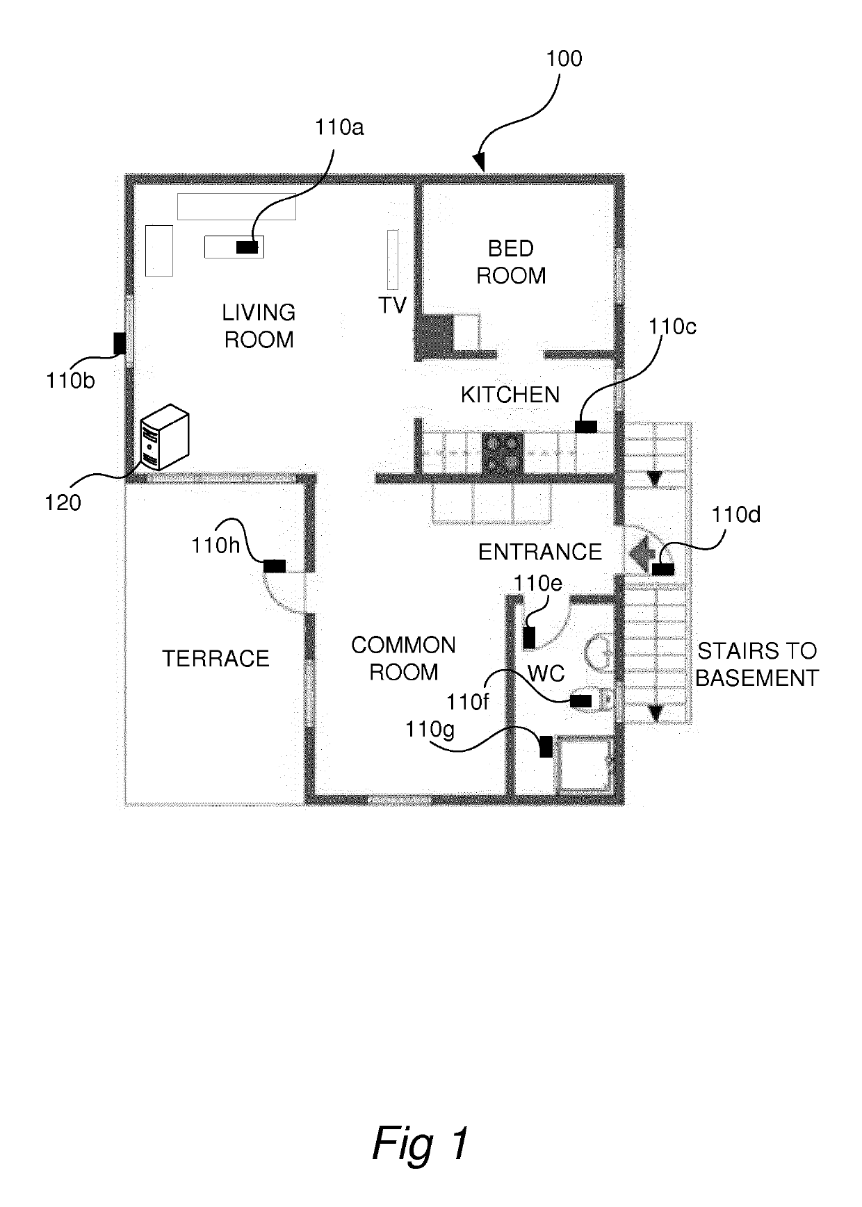
[0040]FIG. 1 shows an example of a building 100, in this example a house, which is arranged with a sensor system (referenced 200 in FIG. 8) according to an embodiment.

[0041]The house has different rooms, such as a kitchen, a bed room, a bathroom (referenced WC in FIG. 1). The house is also arranged with a set of stairs leading down to a basement. The description of this application will be focussed on a few rooms, but it should be noted...


PUM


Abstract

A multi-sensory sensor comprises at least a first and a second sensor element, wherein the multi-sensory sensor is adapted for attachment to a movable structure in a building. The multi-sensory sensor is operatively associated with a controller that is configured to receive input from said first sensor element, wherein the input is indicative of a movement of the movable structure. The controller is further configured to receive input from the second sensor element, and indirectly identify a human behavioral action in the building based on a combination of the input from the first sensor element and the input from the second sensor element. It is further configured to determine a function to be taken based on the identified action, and cause the function to be taken to be executed. In one embodiment the first sensor is a movement sensor element for sensing a movement and the second sensor element is an audio sensor element for sensing audio.

Description

[0001]This is a Continuation Application of U.S. patent application Ser. No. 15 / 698,380, filed 7 Sep. 2017, which is a Continuation Application of U.S. patent application Ser. No. 14 / 913,247, filed 19 Feb. 2016, which is a National Stage Application of PCT / EP2014 / 067840, filed 21 Aug. 2014, which claims benefit of European Patent Application No. 13181268.7, filed 22 Aug. 2013, and which applications are incorporated herein by reference. To the extent appropriate, a claim of priority is made to each of the above disclosed applications.TECHNICAL FIELD[0002]This application relates to a sensor and a system and associated methods for behavioural monitoring.BACKGROUND[0003]In today's society there exist many different monitoring systems which based on an array of different sensors identify an appropriate function to execute based on the received sensor signals.[0004]Monitor systems are becoming increasingly popular for monitoring areas of special interest. Such systems may be surveillanc...

Claims


Application Information

Patent Timeline
Patent Type & Authority Patents(United States)
IPC IPC(8): G08B21/04G08B29/18
CPCG08B21/0492G08B29/183G08B21/0423G08B21/043
Inventor KAY, DAVID
Owner DORO
Why Eureka
Try Eureka