Filament, ionization chamber, and ion-implantation apparatus

a technology of ionization chamber and filament, which is applied in the direction of electrical equipment, electric discharge tubes, basic electric elements, etc., can solve the problems of shortened filament life, high plasma concentration around the bending point of filament, and incongruous plasma concentration near the filamen

Active Publication Date: 2019-05-21
WUHAN CHINA STAR OPTOELECTRONICS SEMICON DISPLAY TECH CO LTD
View PDF10 Cites 0 Cited by
  • Summary
  • Abstract
  • Description
  • Claims
  • Application Information

AI Technical Summary

Benefits of technology

[0007]In order to solve the technical problem, the present application provides a filament, an ionization chamber and an ion-implantation apparatus for solving the problem that: for the filament of the prior art is more likely to break around the bending point after a long time usage, the life time of the filament is short and the maintenance cost of the ion-implantation apparatus and the production cost of the display device are high.
[0028]The beneficial effects of the present application are: the connecting portion is a bent portion of the filament, and the cross-sectional dimensions of the respective portions (the first end portion, the second end portion and the connecting portion) after the filament is bent are the same. Because the resistance of the filament is related with the cross-sectional dimension of the filament, the cross-sectional dimension of the filament is uniform, the resistance of respective portions of the filament is the same, the number of the hot electrons generated at respective portions by powering the filament is the same, the hot electrons and ion-source gas collide to generated plasma, the plasma concentration around the filament is uniform, to avoid the emergence of corrosion of the filament at certain portion caused by an over high plasma concentration, hence, the filament is not easy to break, the filament life is improved, the ion-implantation apparatus maintenance costs and display equipment production costs are reduced.

Problems solved by technology

Hot electrons are generated after applying with current, the ion-source gas into ionization chamber collides the hot electrons to produce plasma, due to the portions of the filament which has larger resistance will produce more hot electrons, the more thermal electrons collide the ion-source gas to produce more plasma, resulting the plasma concentration around the bending points of the filament be higher, the plasma concentration near the filament is not uniform.
The higher plasma concentration is easier to corrode the filament, so that the filament is more likely to break around the bending points after a long time usage, the filament life is shortened, the maintenance costs of ion-implantation apparatus and display equipment production costs is increased.

Method used


Image

  • Filament, ionization chamber, and ion-implantation apparatus
  • Filament, ionization chamber, and ion-implantation apparatus
  • Filament, ionization chamber, and ion-implantation apparatus

Examples


first embodiment

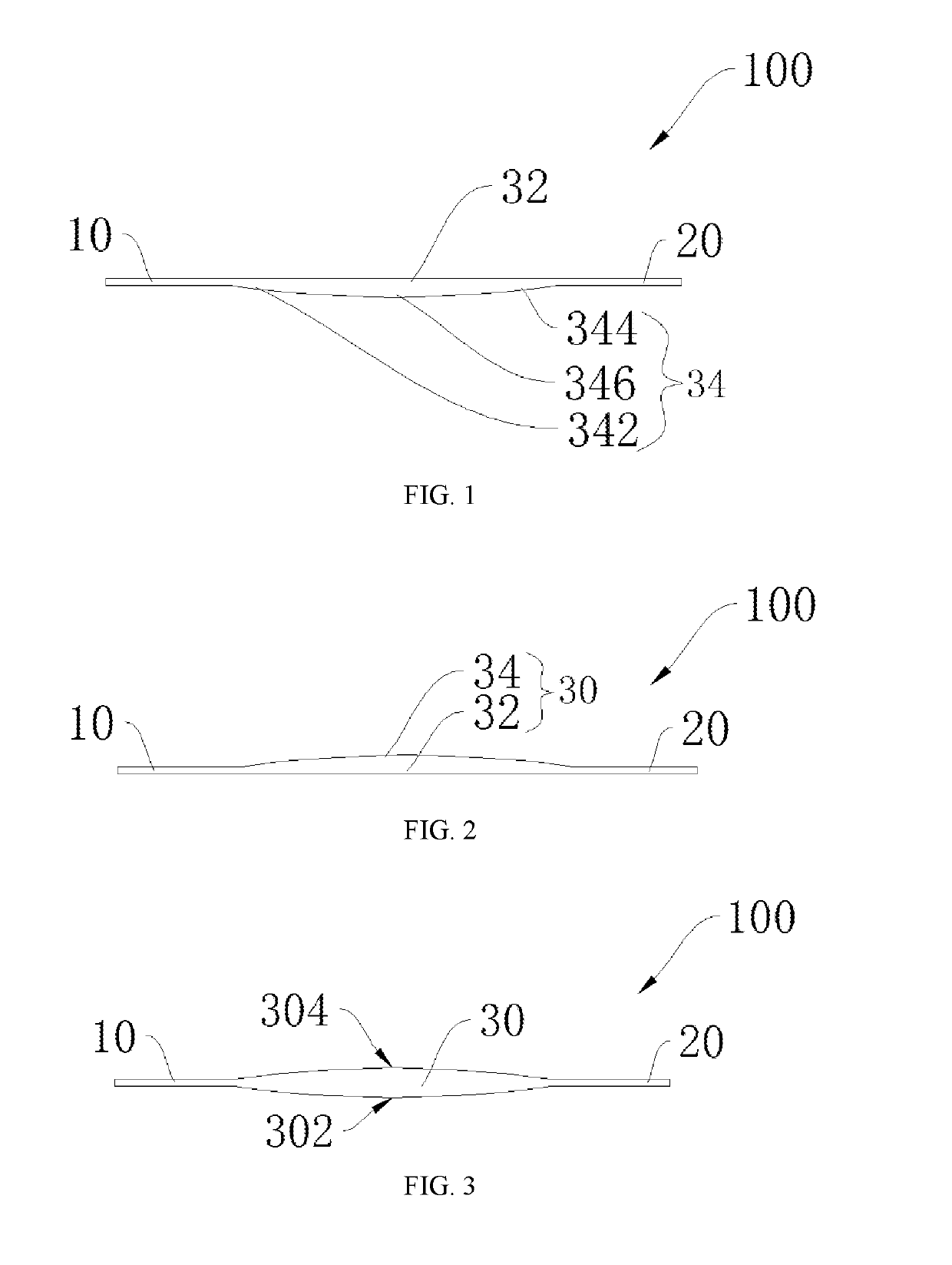
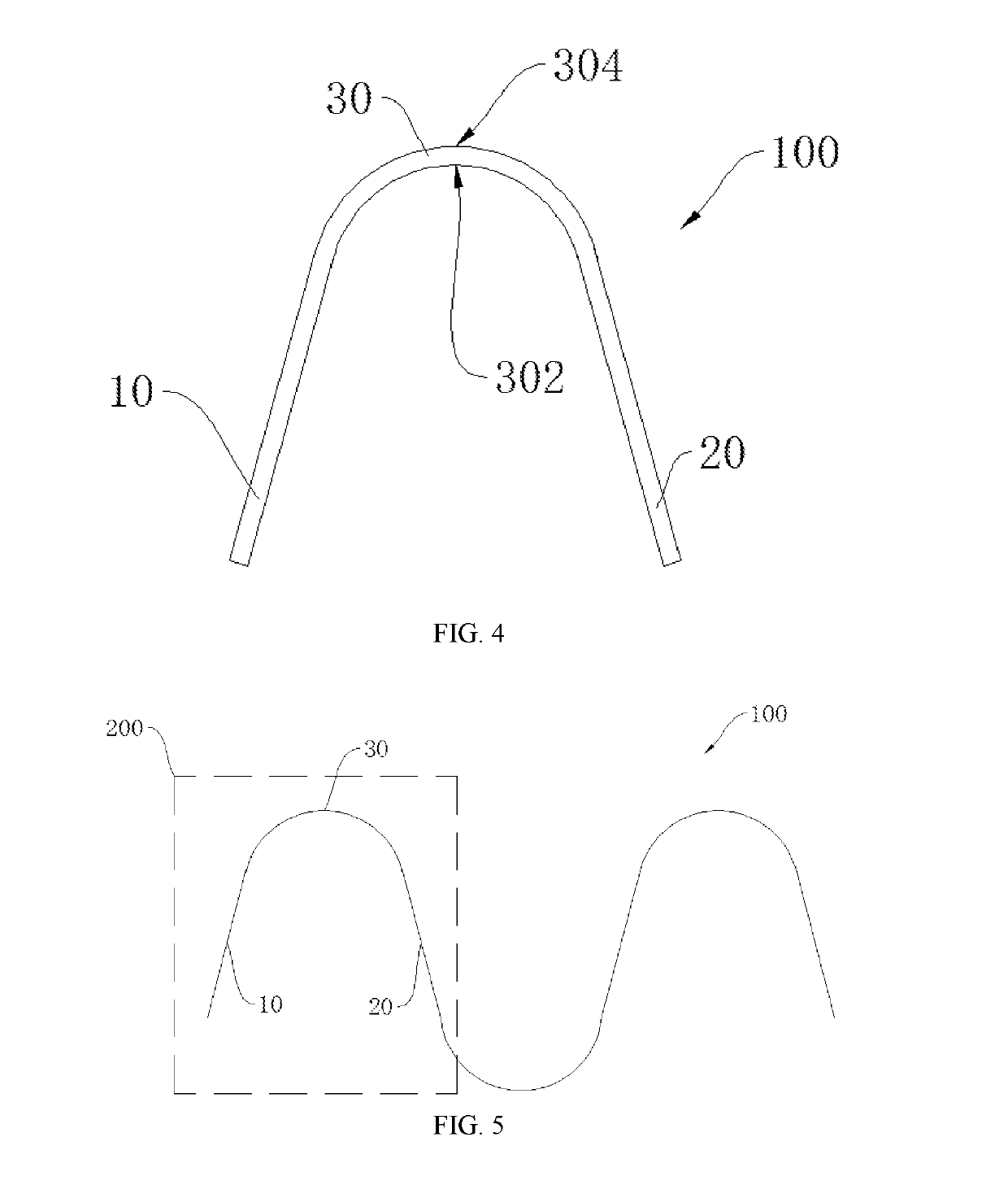
[0038]Please refer to FIGS. 1-4, the filament 100 provided in the present application comprises a first end portion 10, a second end portion 20 and a connecting portion 30. The connecting portion 30 is located between the first end portion 10 and the second end portion 20 and connects the first end portion 10 and the second end portion 20. The first end portion 10 and the second end portion 20 are electrically connected to a power supply device. In one embodiment, the first end portion 10 is provided with a connector at one end away from the connection portion 30 for connecting to the power supply device, the second end portion 20 is also provided with a connector at one end away from the connection portion 30 for connecting to the power supply device, for accessing the power supply device. The filament 100 and the power supply device are connected in series. The power supply device inputs a current to the filament 100 to generate hot electrons. The first end portion 10 is bent with...

second embodiment

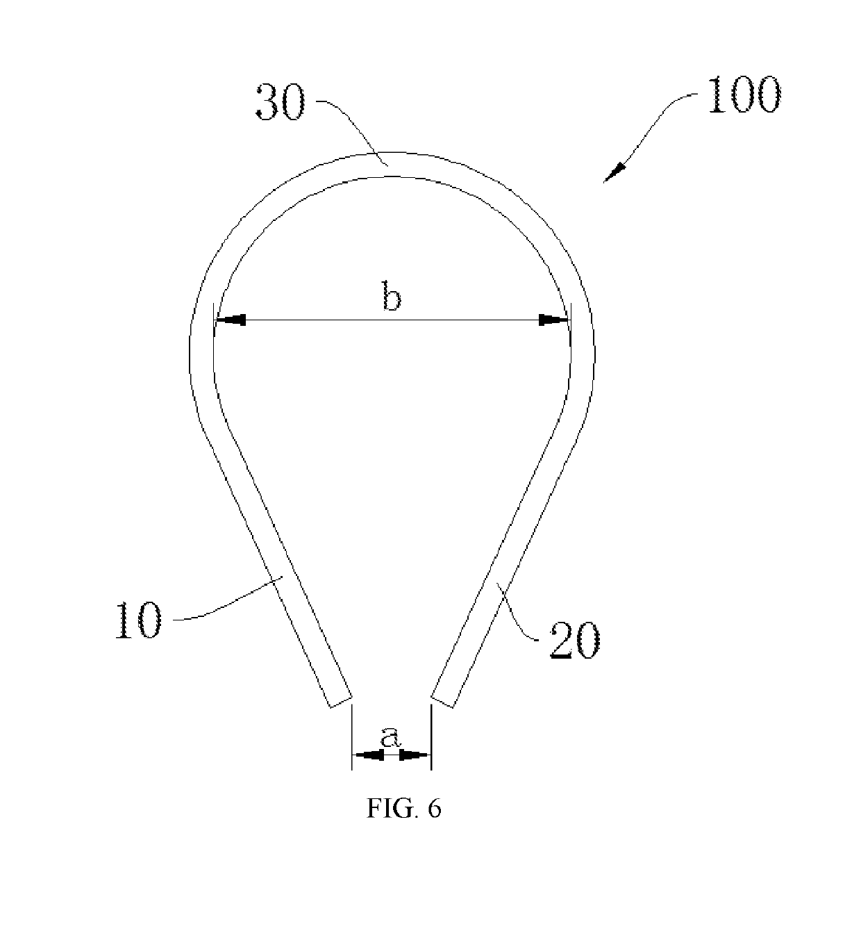
[0047]Please refer to FIGS. 6-7, the filament 100 provided in the present application is bent at the connecting portion 30. A curvature of the connecting portion 30 after bending is not less than π. A distance a between the first end portion 10 and the second end portion 20 is not greater than a bending diameter b (as shown in FIG. 6) of the connecting portion 30. In other embodiments, the distance a between the first end portion 10 and the second end portion 20 is equal to the bending diameter b of the connecting portion 30 (as shown in FIG. 7). The connecting portion 30 is a bent portion of the filament 100, and the cross-sectional dimensions of the respective portions (the first end portion 10, the second end portion 20 and the connecting portion 30) after the filament 100 is bent are the same. Because the resistance of the filament 100 is related with the cross-sectional dimension of the filament 100, the cross-sectional dimension of the filament 100 is uniform, the resistance o...


PUM


Abstract

A filament includes first and second end portions between which a connecting portion is arranged. The first and second end portions are electrically connected to a power supply device. The first end portion is bent with respect to the second end portion through the connecting portion. A cross-sectional dimension of the bent connecting portion is the same as cross-sectional dimensions of the first and second end portions. Also disclosed are an ionization chamber and an ion-implantation apparatus. The cross-sectional dimension of the filament is uniform. The resistance of respective portions of the filament is the same. The number of the hot electrons generated at respective portions by powering the filament is the same. The hot electrons and ion-source gas collide to generated plasma. The plasma concentration around the filament is uniform, to avoid the emergence of corrosion of the filament at certain portion caused by an over high plasma concentration.

Description

CROSS-REFERENCE TO RELATED APPLICATIONS[0001]The present application claims the priority benefit of application serial No. 201710495834.8, entitled “Filament, ionization chamber, and ion-implantation apparatus”, filed on Jun. 26, 2017, which is incorporated herein by reference for all purposes and fully set forth herein.BACKGROUND OF THE APPLICATION[0002]Field of Application[0003]The present application relates to the field of liquid crystal display, and more particularly to a filament, ionization chamber, and ion-implantation apparatus.[0004]Description of Prior Art[0005]Display devices have become an indispensable part of modern life. In the process of low temperature polysilicon (LTPS) thin film transistors and organic light-emitting diodes (OLEDs) for display devices, the ion-implantation apparatus is needed to implant the plasma into the glass substrate. In the ion-implantation apparatus, the ion-source gas evenly enters in the ionization chamber through the air supply pipe, th...

Claims


Application Information

Patent Timeline
Patent Type & Authority Patents(United States)
IPC IPC(8): H01J37/32H01J37/317
CPCH01J37/32541H01J37/3255H01J2237/082H01J37/3171H01J37/32412
Inventor XIE, RUI
Owner WUHAN CHINA STAR OPTOELECTRONICS SEMICON DISPLAY TECH CO LTD
Why Eureka
Try Eureka