Electric motor and blowing apparatus

a technology of electric motors and blowing apparatuses, which is applied in the direction of mechanical energy handling, dynamo-electric machines, supports/enclosements/casings, etc., can solve the problems of increasing and achieve the suppression of temperature increase in bearings, reducing the life of bearings, and reducing the resistance of windings.

Active Publication Date: 2019-05-21
DAIKIN IND LTD
View PDF21 Cites 0 Cited by
  • Summary
  • Abstract
  • Description
  • Claims
  • Application Information

AI Technical Summary

Benefits of technology

[0015]According to the second aspect of the electric motor of the present disclosure, even when a magnetic powder is mixed in air flowing between the rotor hole and the stator hole, an entry of the magnetic powder into the air gap can be suppressed by the protruding part.
[0016]According to the third aspect of the electric motor of the present disclosure, a communication part between the air gap between the stator and the rotor fixing part and the air gap can be kept away from each other.
[0017]According to the fourth aspect of the electric motor of the present disclosure, the air gap between the shaft and the stator as an adiabatic part, so that heat generated in the stator is hardly transferred to the shaft. Thus, a temperature increase in the bearing can be suppressed, and a reduction in a life-span of the bearing can be suppressed.
[0018]According to the fifth aspect of the electric motor of the present disclosure, air flows in a position near the shaft, so that the temperature increase in the bearing can further be suppressed, and the reduction in the life-span of the bearing can be suppressed.
[0019]According to the sixth aspect of the electric motor of the present disclosure, when the air flows from the stator hole to the rotor hole, the air at the entrance side (the stator hole side) flows near the shaft. Since the air at the entrance side is cooler than that of an exit side (the rotor hole side), the temperature increase in the shaft can be suppressed.
[0020]According to the first aspect of the blowing apparatus of the present disclosure, the air is flowed inside the electric motor by the fan, so that the temperature increase in the electric motor can be effectively suppressed.

Problems solved by technology

The temperature increase causes an increase in resistance of a winding of the stator, for example, and thereby is not desirable.

Method used


Image

  • Electric motor and blowing apparatus
  • Electric motor and blowing apparatus
  • Electric motor and blowing apparatus

Examples


Embodiment Construction

)

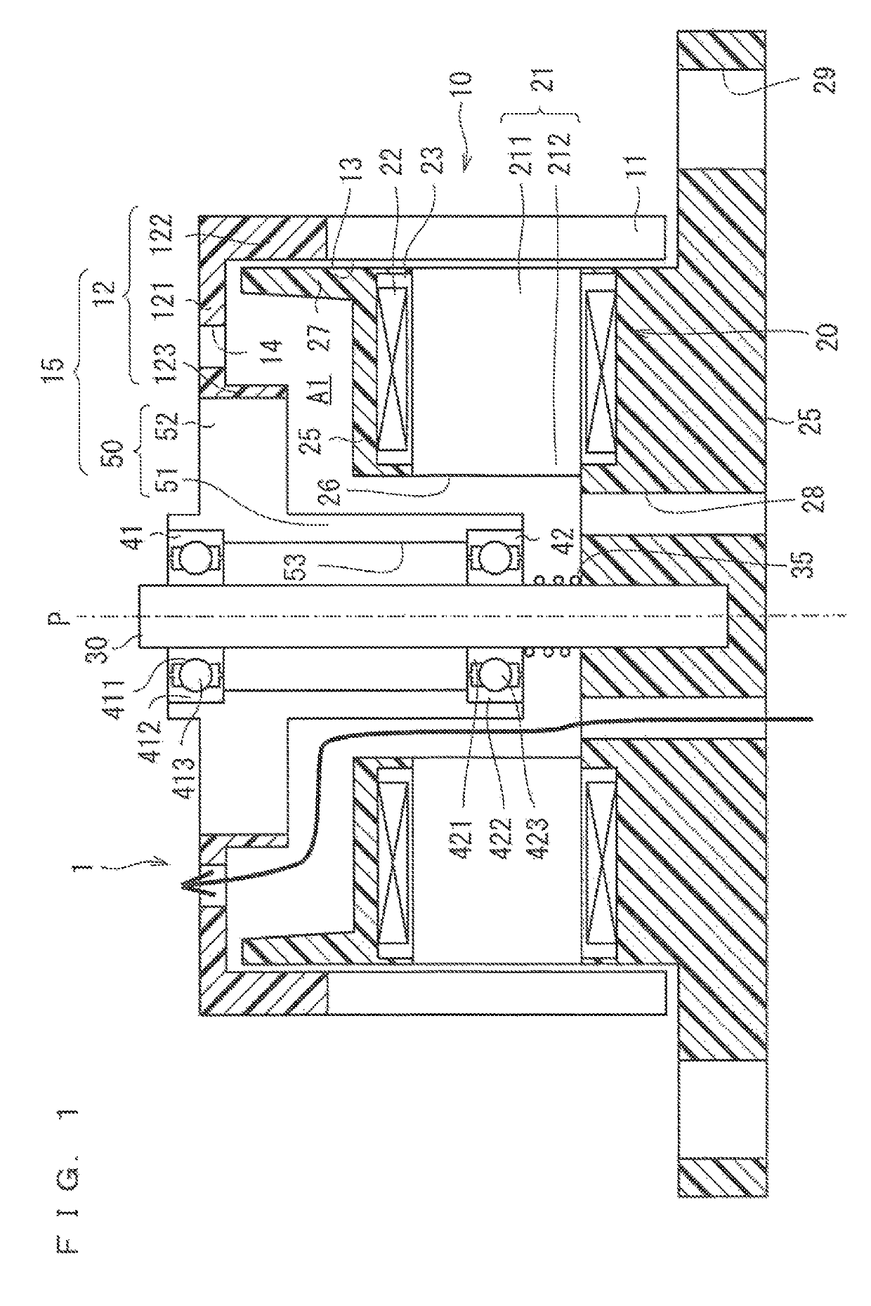
[0028]FIG. 1 is a sectional view of an example of a schematic configuration of an electric motor 1, illustrating the configuration of the electric motor 1 in a section including an imaginary axis of rotation P. The electric motor 1 includes a rotor 10, a stator 20, a shaft 30, a plurality of bearings 41 and 42, and a bearing housing 50.

[0029]The shaft 30 is a rod-shaped (for example, columnar) member extending along the axis of rotation P and has conductivity. The shaft 30 is made of, for example, metal such as stainless steel.

[0030]In the following description, a direction extending along the axis of rotation P is referred to as an axial direction, and a circumferential direction and a radial direction with respect to the axis of rotation P are merely referred to as a circumferential direction and a radial direction, respectively.

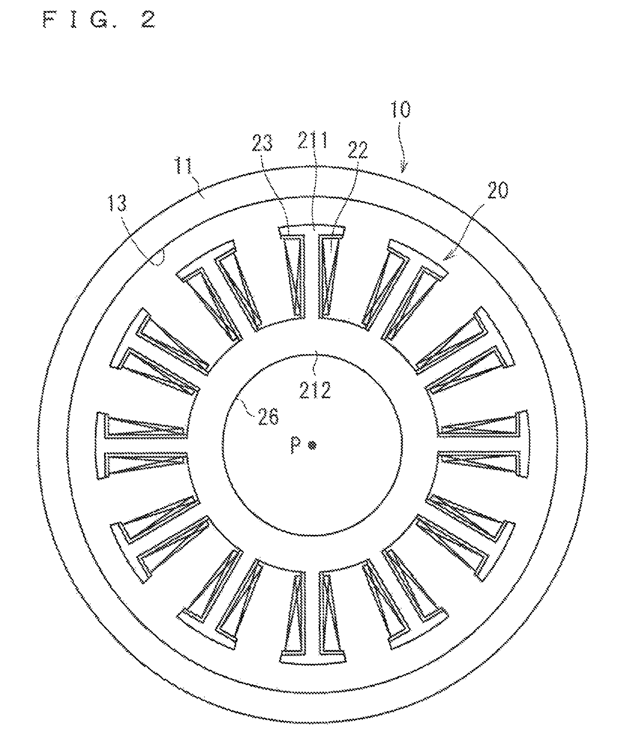
[0031]The stator 20 includes a stator core 21 and a winding 22. The stator core 21 is made of a soft magnetic material and has conductivity. The stator c...


PUM


Abstract

An electric motor includes a shaft extending along an axial direction, a stator, a rotor arranged farther away from the shaft than the stator in a radial direction of the shaft, a stator fixing part fixed to the shaft and fixed to the stator, and a rotor fixing part facing the stator fixing part and the stator with an air gap formed between in the axial direction. The rotor fixing part is rotatably coupled to the shaft and fixed to the rotor. A rotor hole is formed in the rotor fixing part. The rotor hole passes through the rotor fixing part to be communicated with the air gap. A stator hole is formed in the stator fixing part. The stator hole passes through the stator fixing part to be communicated with the rotor hole with the air gap formed between.

Description

CROSS-REFERENCE TO RELATED APPLICATIONS[0001]This U.S. National stage application claims priority under 35 U.S.C. § 119(a) to Japanese Patent Application No 2014-133976, filed in Japan on Jun. 30, 2014, the entire contents of which are hereby incorporated herein by reference.TECHNICAL FIELD[0002]The present disclosure relates to an electric motor and a blowing apparatus.BACKGROUND ART[0003]Japanese Patent No 3513654 describes an electric motor. According to Japanese Patent No. 3513654, the electric motor includes a stator and a rotor. The rotor faces the stator from an outer periphery side of the stator with an air gap therebetween. A shaft is disposed to pass through the stator. The stator is fixed to one end of the shaft so as not to rotate about the shaft, and the rotor is rotatably fixed to the shaft with a bearing therebetween. As a result, the rotor is rotatably fixed to the stator. The above electric motor drives an axial fan.[0004]Japanese Patent Application Laid-Open No 10-...

Claims


Application Information

Patent Timeline
Patent Type & Authority Patents(United States)
IPC IPC(8): H02K9/06H02K7/14H02K5/20H02K7/08
CPCH02K9/06H02K7/14H02K5/20H02K7/086H02K5/207
Inventor TAKAYAMA, YOSHINORITSUKIDA, JUNJI
Owner DAIKIN IND LTD
Why Eureka
Try Eureka