Pleural air leak test system

a pleural air leak and test system technology, applied in the field of pleural air leak test systems, can solve the problems of varying levels of reliability and satisfaction, difficult to detect the location of pleural air leaks, and expensive and time-consuming apparatus,

Active Publication Date: 2019-05-28
NEOMEND INC
View PDF21 Cites 0 Cited by
  • Summary
  • Abstract
  • Description
  • Claims
  • Application Information

AI Technical Summary

Benefits of technology

[0010]Some embodiments provide a pressurized canister for facilitating identification of pleural air leaks, the pressurized canister comprising a canister capable of holding a pressurized fluid; a pressurized fluid comprising one or more indicator compounds.
[0011]Some embodiments provide a pleural air leak detection kit, the kit comprising a pressurized canister for facilitating identification of pleural air leaks, the pressurized canister comprising a canister capable of holding a pressurized fluid, a pressurized fluid comprising one or more indicator compounds; and a dispenser apparatus for housing and actuating the pressurized canister, wherein the dispenser apparatus has a dispensing end capable of coupling to a breathing apparatus to permit flow of indicator compound into the lungs via the breathing apparatus.

Problems solved by technology

Detecting the location of a pleural air leak is a difficult task.
These methods offer varying levels of reliability and satisfaction but are not consistently sensitive and accurate, and require the use of costly and time intensive apparatus, and may require that the patient be moved.
Often in current surgical practice a surgeon does not perform a leak test at all, for many reasons, including but not limited to time demands, the physical manipulation needed to submerge the lung, the difficulty observing leaks on the posterior lung, and the difficulty in tracking an air bubble to its origin, difficulty in recognizing or marking the location for later treatment, etc.

Method used


Image

  • Pleural air leak test system
  • Pleural air leak test system

Examples


Embodiment Construction

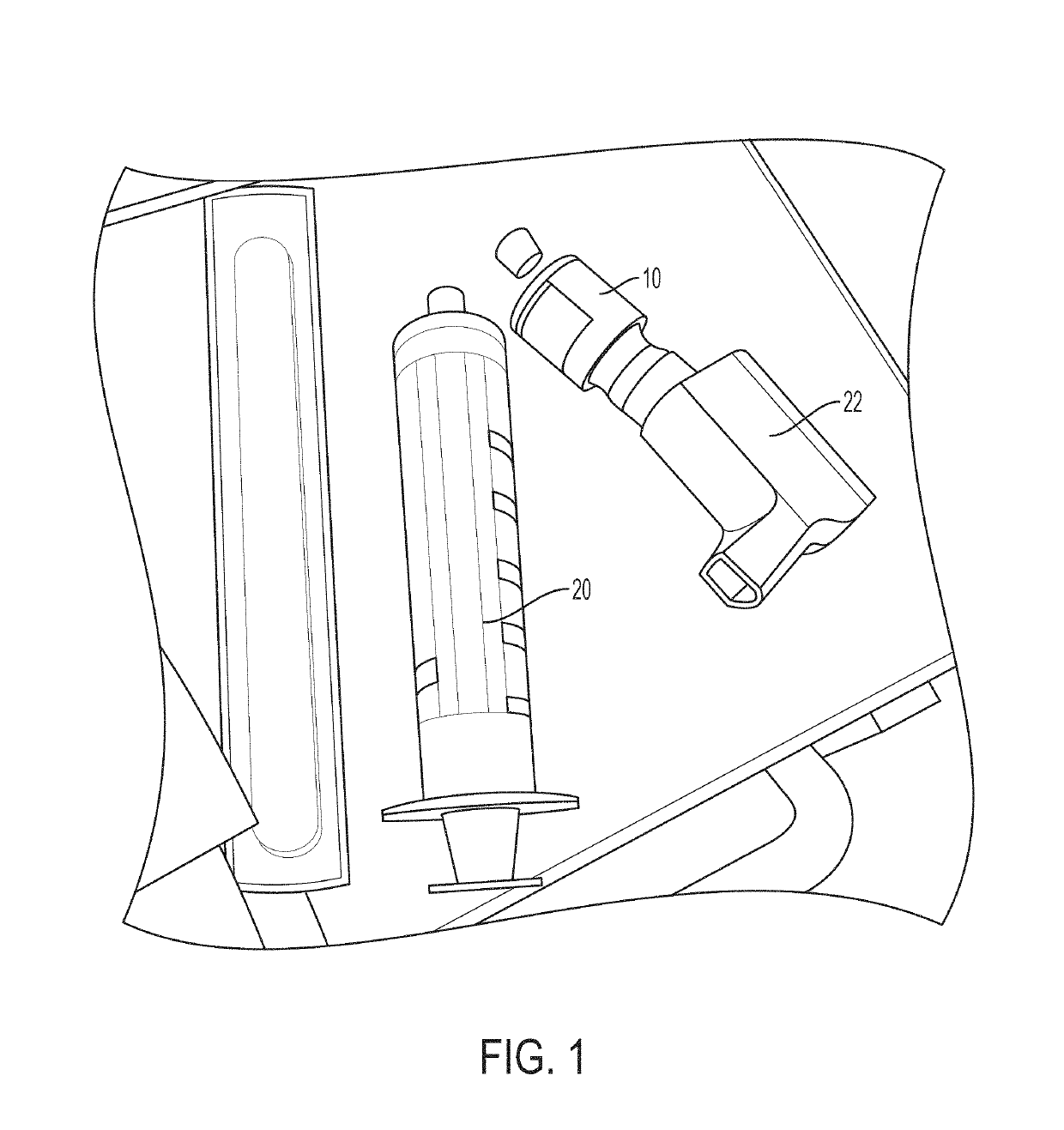
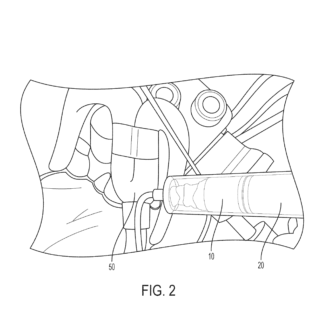
[0016]Identifying and marking one or more pleural air leaks can be easily and conveniently accomplished by introducing an identifier, such as a stain or dye, into the lung. Introduction into the lung is accomplished by aerosolizing the stain or dye so it may travel through the airway(s). The identifier can be introduced to the lung via the normal airways, for example via the trachea, either or both of the main bronchi, or if desired at some other location. Upon introduction, the stain will travel most readily into the path or paths of least resistance, which will correspond to paths terminating in an air leak. The identifier will localize in or through the pathways ending in an air leak. On the exterior surface of the lung, the identifier will become visible, as it colors the exposed tissue at the leak site. Without the identifier, the exposed tissue is nearly impossible to distinguish from surrounding tissue. Once the identifier works its way through the pathway, it will be readily...


PUM

PropertyMeasurementUnit
resistanceaaaaaaaaaa
colorsaaaaaaaaaa
biocompatibleaaaaaaaaaa

Abstract

Disclosed are methods, apparatus, and systems useful for detecting leaks in pleural tissue. Also disclosed are methods of detecting and sealing such leaks. Indicator dye or stain is aerosolized and delivered to the lung via anesthetic equipment, oxygen tube, endoscope, or other suitable equipment, the dye is allowed to travel through the lung along the path or paths of least resistance emerging at the surface of the lung, staining the tissue indicative of a leak. Some embodiments include introducing one part of a two part sealant with the dye, and applying the second part of the sealant to the stain identified leak locations.

Description

CROSS-REFERENCE TO RELATED APPLICATIONS[0001]This application claims priority to U.S. Provisional No. 62 / 016,898 entitled “PLEURAL AIR LEAK TEST SYSTEM” filed Jun. 25, 2014, which is hereby incorporated by reference in its entirety.FIELD[0002]Disclosed are methods, apparatus, and systems useful for detecting leaks in pleural tissue. Also disclosed are methods of detecting and sealing such leaks.BACKGROUND[0003]Detecting the location of a pleural air leak is a difficult task. Current methods include high resolution cat scans, MRIs, and bronchoscopy for direct visualization of proximal airway leaks and bronchopleural fistulas. These methods offer varying levels of reliability and satisfaction but are not consistently sensitive and accurate, and require the use of costly and time intensive apparatus, and may require that the patient be moved. One of the most definitive means to identify a pleural air leak is through the relatively crude technique of open thoracotomy, in which the chest...

Claims


Application Information

Patent Timeline
Patent Type & Authority Patents(United States)
IPC IPC(8): A61B5/00A61M13/00A61M16/08A61L24/00A61L24/10A61B5/08A61L24/04A61M11/00A61B17/00
CPCA61M13/003A61B5/08A61B17/0057A61L24/001A61L24/0026A61L24/043A61M16/0816A61L24/108A61M2205/584A61B2017/0065A61B2017/00495A61M11/00A61M2202/0488A61M2205/15
Inventor DAVIS, PETER G.
Owner NEOMEND INC
Why Eureka
Try Eureka