
Support structure for rotating shafts of vehicle

a technology for supporting structures and electric motors, which is applied in the direction of hybrid vehicles, couplings, transportation and packaging, etc., can solve the problems of reducing the butting force of the spline teeth, reducing and preventing the application of excessive loads to the bearings. , to achieve the effect of reducing the butting noise of the tooth due to a torque variation transmitted from the engine, preventing application, and limiting the performance of the elastic member

Inactive Publication Date: 2019-05-28
TOYOTA JIDOSHA KK
View PDF31 Cites 3 Cited by
  • Summary
  • Abstract
  • Description
  • Claims
  • Application Information

AI Technical Summary

Benefits of technology

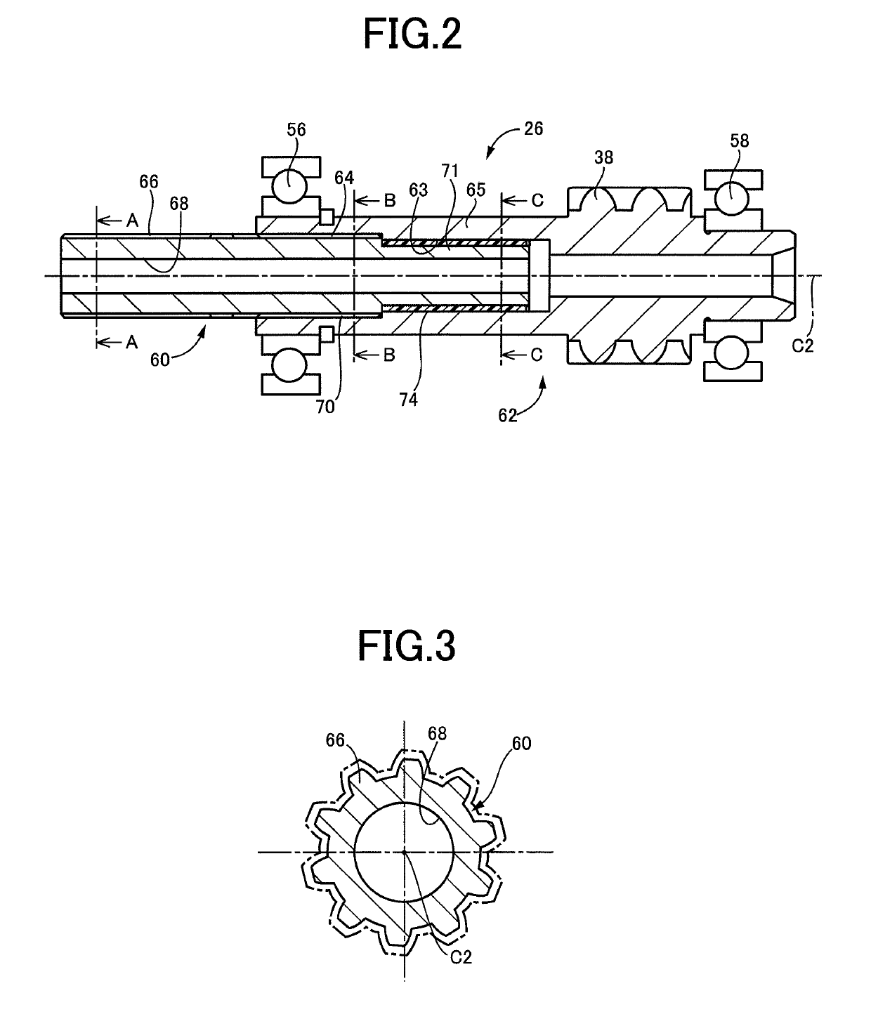
[0015]As described above, one of the rotor shaft and the drive shaft is constituted by the first rotary shaft and the second rotary shaft, and the elastic member is interposed between the first and second rotary shafts such that the first and second rotary shafts are operatively connected to each other through the elastic member, so that the tooth butting noise due to a torque variation transmitted from the engine can be reduced by the elastic member. Further, the rotor shaft of the electric motor and the drive shaft are assembled with respect to each other after the rotor shaft or the drive shaft is assembled in advance such that the elastic member is interposed between the first rotary shaft and the second rotary shaft. Namely, the elastic member is installed upon assembling of the first rotary shaft and the second rotary shaft in advance, so the load required for installation of one of the rotor shaft and the drive shaft while the other of the rotor shaft and the drive shaft is supported by a ball bearing or bearings is not increased in the presence of the elastic member, making it possible to prevent application of an excessive load to the ball bearing or bearings upon installation of the above-indicated one of the rotor shaft and the drive shaft. In addition, it is not necessary to limit the performance of the elastic member since the elastic member is installed upon assembling of the first rotary shaft and the second rotary shaft with respect to each other, so that the function of the elastic member to reduce the tooth butting noise can be greatly improved.
[0016]In the support structure according to the second aspect of the invention, the rotor shaft and the drive shaft can be assembled with respect to each other, after assembling of the drive shaft such that the elastic member is interposed between the first and second rotary shafts. Accordingly, it is possible to prevent application of an excessive load to the ball bearing or bearings upon assembling of the rotor shaft and the drive shaft with respect to each other. In addition, the tooth butting noise due to the torque variation transmitted from the engine can be reduced by the elastic member provided in the drive shaft.
[0017]In the support structure according to the third aspect of the invention, the rotor shaft and the drive shaft can be assembled with respect to each other, after assembling of the rotor shaft such that the elastic member is interposed between the first and second rotary shafts. Accordingly, it is possible to prevent application of an excessive load to the ball bearing or bearings upon assembling of the rotor shaft and the drive shaft with respect to each other. In addition, the tooth butting noise due to the torque variation transmitted from the engine can be reduced by the elastic member provided in the rotor shaft.
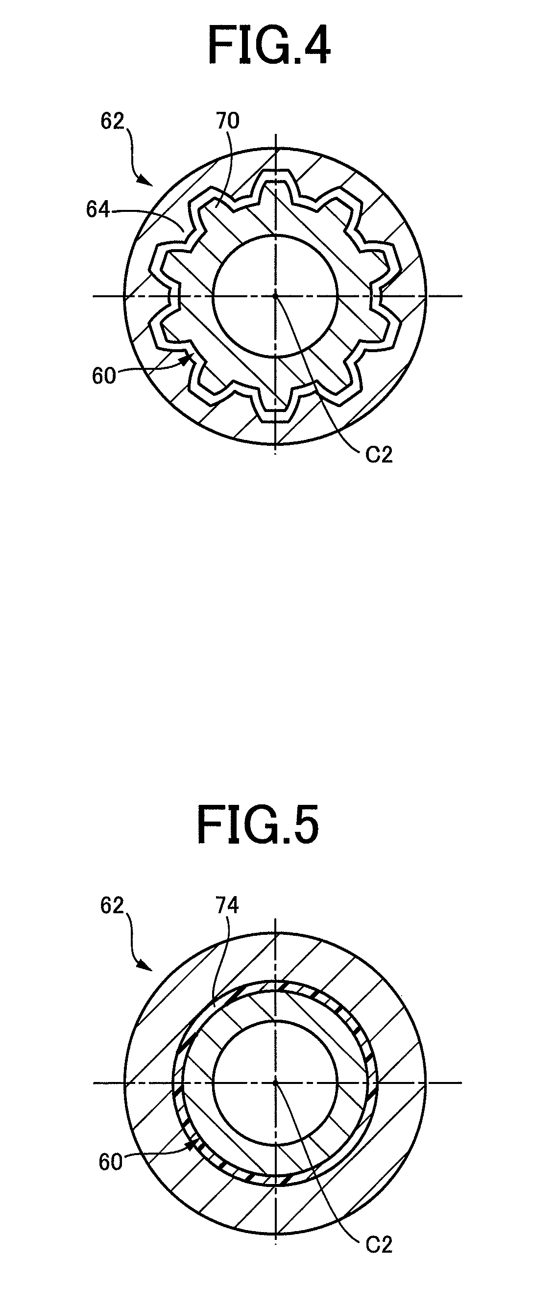
[0018]In the support structure according to the fourth aspect of the invention, the elastic member is disposed in the radial gap formed between the axial portions of the first rotary shaft and the second rotary shaft which overlap each other, so that the tooth butting force to be generated upon mutual butting of spline teeth of the first rotary shaft and spline teeth of the second rotary shaft against each other is reduced by the elastic member, whereby the tooth butting noise is reduced. Further, since the elastic member is to be interposed between the first rotary shaft and the second rotary shaft, the first rotary shaft, the second rotary shaft, and the elastic member are assembled in advance with respect to each other, so that it is possible to prevent application of an excessive load to the ball bearing or bearings upon assembling of the rotor shaft and the drive shaft with respect to each other.
[0019]In the support structure according to the fifth aspect of the invention, the first rotary shaft and the second rotary shaft are connected to each other through the elongate member, so that the elongate member is torsionally twisted upon mutual butting of spline teeth of the first rotary shaft and spline teeth of the second rotary shaft against each other, whereby the force of the mutual butting of the spline teeth of the first and second rotary shafts against each other is reduced, and the tooth butting noise is reduced. Further, the elongate member is installed upon assembling of the first and second rotary shafts with respect to each other, so that it is possible to prevent application of an excessive load to the ball bearing or bearings upon assembling of the rotor shaft and the drive shaft with respect to each other.
[0020]In the support structure according to the sixth aspect of the invention, the drive shaft and the power transmitting shaft are operatively connected to each other through the helical gear, so that the first rotary shaft and the second rotary shaft are moved in the thrust direction (in the axial direction) due to a force acting on the drive shaft and the rotor shaft in the thrust direction when a drive force is transmitted between the drive shaft and the power transmitting shaft. However, the second elastic member permits damping of a shock of an abutting contact between the members axially adjacent to each other upon movements in the thrust direction of the first rotary shaft, the second rotary shaft, and the member to be moved together with the first or second rotary shaft.
[0021]In the support structure according to the seventh aspect of the invention, the elongate member is torsionally twisted prior to the mutual butting of the external spline teeth of the first rotary shaft and the internal spline teeth of the second rotary shaft against each other, when a torque is transmitted to the drive shaft, whereby the butting force is reduced, and the butting noise is reduced.

Problems solved by technology

This force of resistance causes an increase of a load (installation load) required to assemble the two rotating shafts together, giving rise to a risk of application of an excessive load to the bearings supporting the above-indicated one rotating shaft.
Accordingly, the function of the elastic member is limited due to limitation of the installation load upon assembling of the two rotating shafts, so that the butting force of the spline teeth cannot be reduced as needed.

Method used


Image

  • Support structure for rotating shafts of vehicle
  • Support structure for rotating shafts of vehicle
  • Support structure for rotating shafts of vehicle

Examples


first embodiment

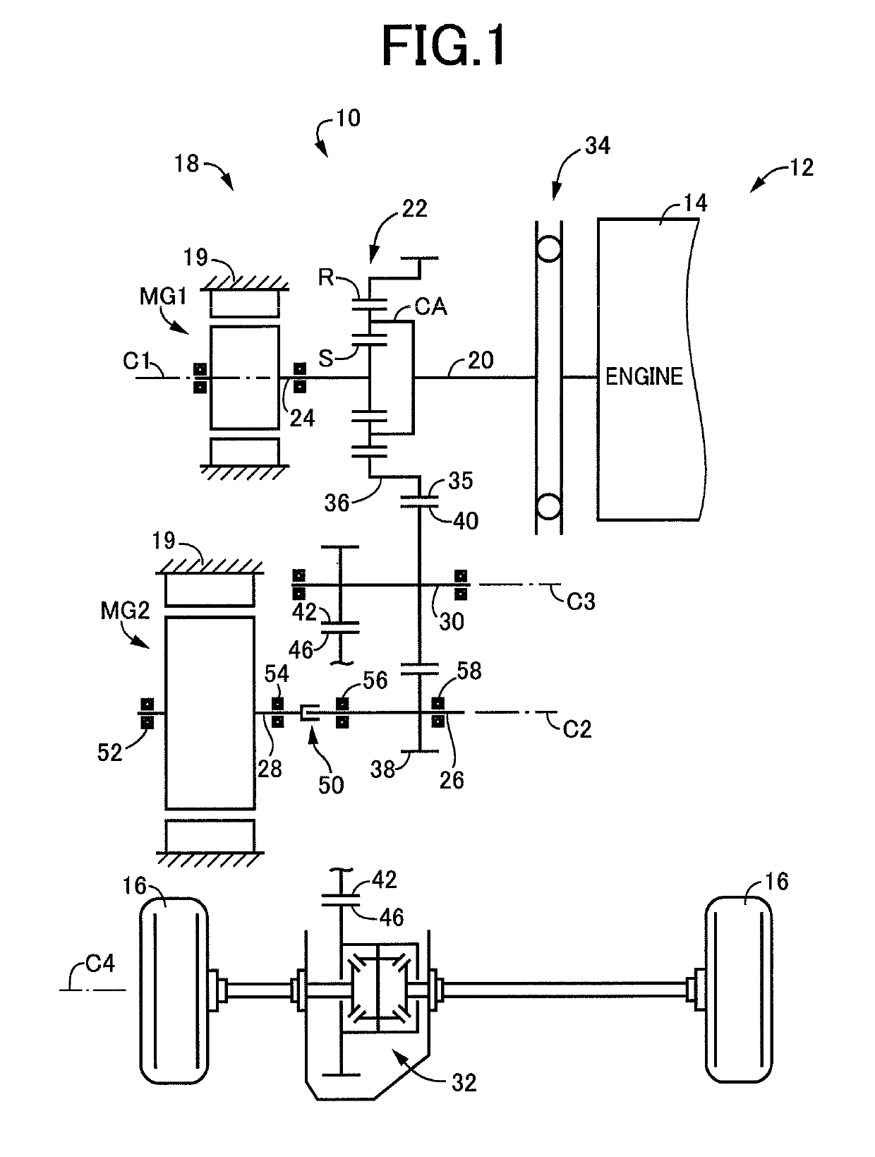
[0035]FIG. 1 is the schematic view for explaining a structure of a drive system 12 provided in a hybrid vehicle 10 (vehicle), to which the present invention is applicable. The drive system 12 includes an engine 14 such as a known gasoline engine or diesel engine functioning as a vehicle drive power source (drive power source), and a vehicular power transmitting system 18 (hereinafter referred to as “power transmitting system 18) through which a drive force of the engine 14 is transmitted to drive wheels 16. The power transmitting system 18 has four rotary axes (C1-C4) parallel to each other, which are disposed within a stationary member in the form of a casing 19. The first axis C1 is coaxial with an axis of rotation of the engine 14, and an output shaft 20, a power distributing mechanism 22, and a first rotor shaft 24 of a first electric motor MG1 are rotatably supported on the first axis C1. A speed reduction shaft 26 and a second rotor shaft 28 of a second electric motor MG2 are ...

second embodiment

[0057]FIG. 7 shows the structure of a speed reduction shaft 100 in another embodiment of this invention. FIG. 7 is the cross sectional view showing the overall arrangement of the speed reduction shaft 100. FIG. 8 is the cross sectional view taken along line A-A of FIG. 7, while FIG. 9 is the cross sectional view taken along line B-B of FIG. 7. As shown in FIG. 7, the speed reduction shaft 100 is constituted by a first rotary shaft 102 spline-coupled to the second rotor shaft 28 of the second electric motor MG2, and a second rotary shaft 104 having the speed reduction gear 38 formed thereon. The first rotary shaft 102 is fitted in an axial bore 105 formed in the second rotary shaft 104.

[0058]The first rotary shaft 102 has an external spline teeth 106 formed on an outer circumferential surface of its axial end portion remote from the ball bearing 58 (on the side of the second electric motor MG2), so that the first rotary shaft 102 is spline-coupled to the second rotor shaft 28 through...

third embodiment

[0068]FIG. 10 is the cross sectional view showing the overall arrangement of a speed reduction shaft 150 in a further embodiment of the invention.

[0069]As shown in FIG. 10, the speed reduction shaft 150 is constituted by a first rotary shaft 152 spline-coupled to the second rotor shaft 28 of the second electric motor MG2 and a second rotary shaft 154 having the speed reduction gear 38 formed thereon. The first rotary shaft 152 is fitted in an axial bore 155 formed in the second rotary shaft 154.

[0070]Unlike the speed reduction shaft 100 described above, the speed reduction shaft 150 in the present embodiment is provided with buffer members described below, respectively between the first rotary shaft 152 and the second rotor shaft 28, between the first rotary shaft 152 and the second rotary shaft 154, and between the ball bearing 58 supporting the speed reduction shaft 150 (second rotary shaft 154), and the casing 19. The speed reduction shaft 150 will be described with respect to it...


PUM


Abstract

A support structure for rotating shafts of a vehicle, including: a drive shaft operatively connected to a power transmitting shaft to which a drive force of an engine is transmitted; and a rotor shaft of an electric motor spline-coupled to the drive shaft, each of the rotor shaft of the electric motor and the drive shaft is being supported by at least one bearing, in the support structure, one of the rotor shaft and the drive shaft is constituted by a first rotary shaft and a second rotary shaft which are operatively connected to each other, and an elastic member is interposed between the first rotary shaft and the second rotary shaft such that the first and second rotary shafts are operatively spline-connected to each other through the elastic member.

Description

CROSS REFERENCE TO RELATED APPLICATIONS[0001]This application is a National Stage of International Application No. PCT / JP2015 / 086117 filed Dec. 24, 2015, claiming priority based on Japanese Patent Application No. 2015-001896 filed Jan. 7, 2015, the contents of all of which are incorporated herein by reference in their entirety.TECHNICAL FIELD[0002]The present invention relates to a support structure for a rotor shaft of an electric motor provided in a hybrid vehicle, and a drive shaft spline-coupled to the rotor shaft, and more particularly to a mechanism for damping a tooth butting noise generated in a spline-coupling portion between the rotor shaft and the drive shaft.BACKGROUND ART[0003]A hybrid vehicle having an engine and an electric motor as a drive power source device is arranged such that a rotor shaft of the electric motor is spline-coupled to a suitable drive shaft. Patent Document 1 discloses an example of this arrangement wherein a drive shaft 18 is spline-coupled to a r...

Claims


Application Information

Patent Timeline
Patent Type & Authority Patents(United States)
IPC IPC(8): B60K6/40F16F15/136F16D1/04F16D3/12F16F15/126F16D3/76B60K6/445F16D3/64B60K6/36
CPCB60K6/40B60K6/445F16D1/04F16D3/12F16D3/76F16F15/126F16F15/136F16D3/64Y02T10/6239B60K6/36F16C3/023F16C19/54F16F2236/106Y02T10/62B60K6/26B60Y2200/92F16D1/02F16D3/14F16D3/50
Inventor YOKOUCHI, YOSHIMITSUKUWAMOTO, HIROKIISOMURA, HARUOICHIKAWA, AKITAKAENDO, HIROATSU
Owner TOYOTA JIDOSHA KK
Learn More