Large kitchen waste heat recovery multi-element utilization device

A waste heat recovery and kitchen technology, which is applied in the direction of steam generation method using heat carrier, indirect heat exchanger, heat exchanger type, etc., can solve the problems of inability to meet various types of heat demand in the kitchen, and single utilization form of waste heat resources in the kitchen , to achieve the effect of compact structure, centralized utilization of heat, and reduction of energy consumption

Active Publication Date: 2021-07-20
SHANDONG UNIV OF TECH
View PDF7 Cites 1 Cited by
  • Summary
  • Abstract
  • Description
  • Claims
  • Application Information

AI Technical Summary

Problems solved by technology

[0004] The purpose of the present invention is to provide a large-scale kitchen waste heat recovery and multi-utilization device, which solves the problem that the current utilization of kitchen waste heat resources is single, and only prepares hot water, hot air, etc., which cannot meet the various heat needs of the kitchen, so additional energy is needed to The problem of preparing steam, hot water and cold

Method used


Image

  • Large kitchen waste heat recovery multi-element utilization device
  • Large kitchen waste heat recovery multi-element utilization device
  • Large kitchen waste heat recovery multi-element utilization device

Examples


Embodiment 1

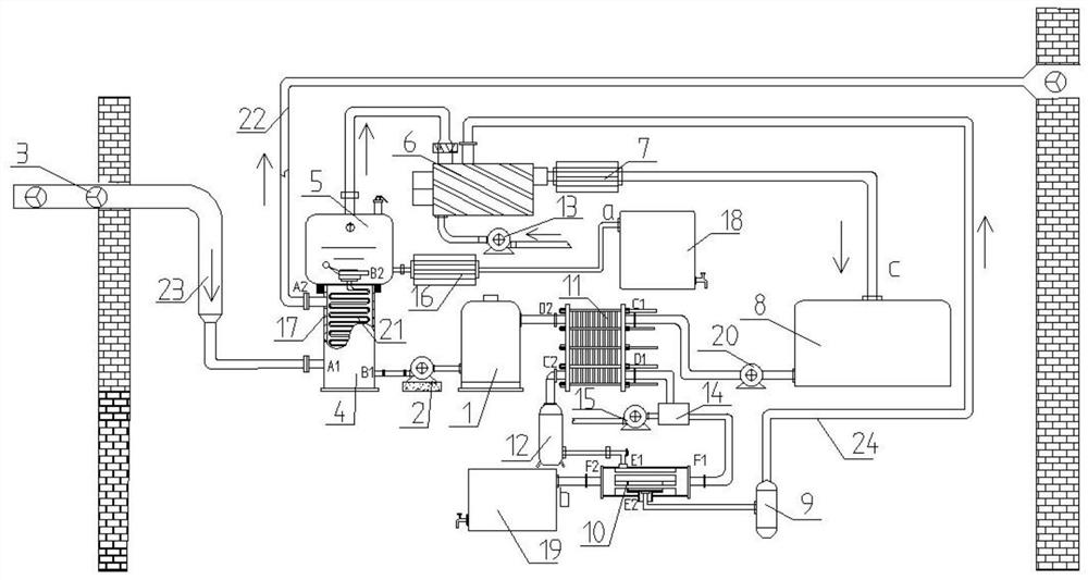
[0028] Example 1, such as Figures 1 to 2 As shown, the present invention is a large-scale kitchen waste heat recovery multiple utilization device, including a heat exchanger 4 connected to the air outlet of the range hood, and the heat exchanger 4 is also connected with a water collection bucket 1, an exhaust pipe 22 and a flash evaporator 5, The steam outlet on the top of the flash evaporator 5 is connected to the steam utilization device 8, the bottom of the flash evaporator 5 is connected to a warm water tank 18, the waste water discharge pipe of the steam utilization device 8 is connected to a heat exchanger 2 11, and the heat exchanger 2 11 is connected to the water collection bucket 1 And the liquid storage tank 12, the liquid storage tank 12 is connected with the economizer 10, and the economizer 10 is connected with the cold water tank 19.

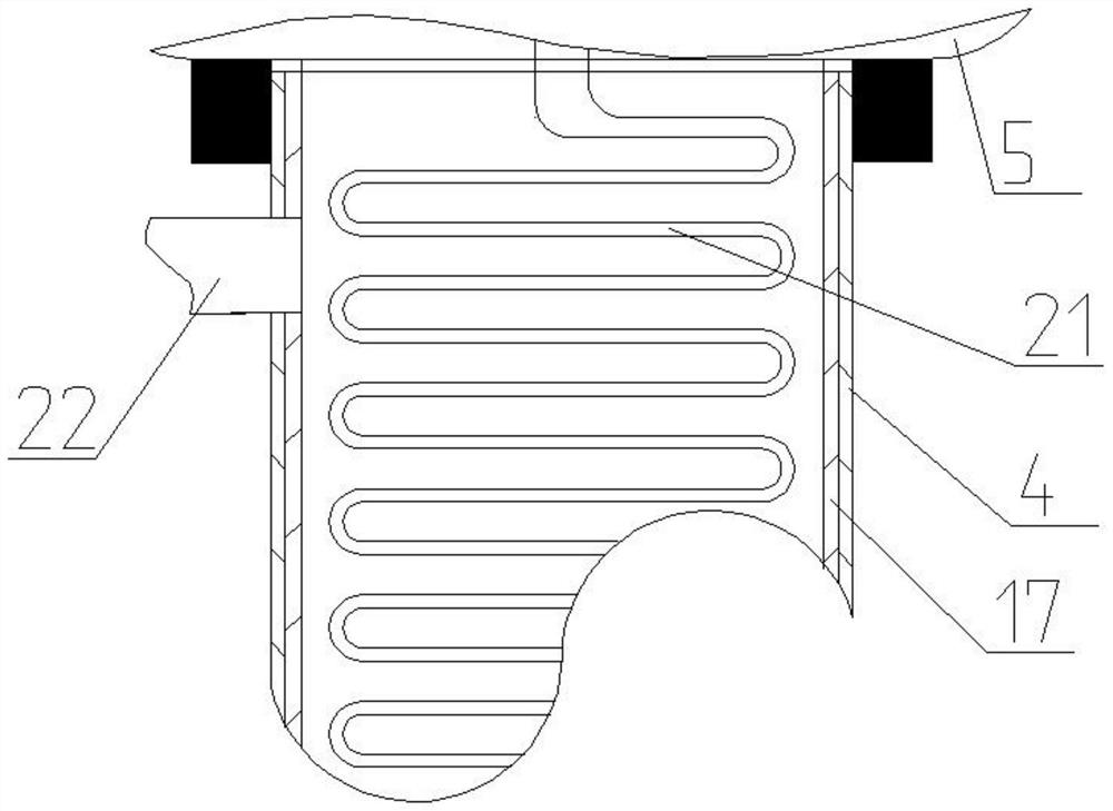
[0029] The heat exchanger-4 is provided with a heat exchange coil 21, one end of the heat exchange coil 21 is connected to the c...

Embodiment 2

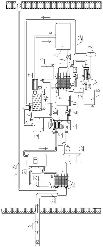
[0044] Embodiment 2 is different from Embodiment 1 in that the outlet of the heat exchanger 4 is connected to the expansion valve 29, the expansion valve 29 is connected to the liquid storage tank 26, the liquid storage tank 26 is connected to the evaporator 25, and the refrigerant in the evaporator 25 The outlet is connected to the gas-liquid separator 27, the gas-liquid separator 27 is connected to a refrigerant compressor 28, the outlet of the refrigerant compressor 28 is connected to the inlet of the heat exchanger-4, the air inlet of the evaporator 25 is connected to the air inlet pipe 23, and the evaporator The air outlet of 25 is connected with the exhaust pipe 22, and the inner wall of the heat exchange pipe where the evaporator 25 communicates with the exhaust pipe 22 is coated with a non-stick coating.

[0045] In summary, the present invention uses the refrigerant to absorb the heat of the hot air discharged from the range hood through the evaporator. After absorbing...


PUM


Abstract

The invention relates to a large kitchen waste heat recovery multi-element utilization device. The large kitchen waste heat recovery multi-element utilization device comprises a first heat exchanger connected with an air outlet of a range hood, the first heat exchanger is further connected with a water collecting barrel, an air outlet pipe and a flash evaporator, a steam outlet in the top of the flash evaporator is connected with steam utilization equipment, the lower portion of the flash evaporator is connected with a warm water tank, a waste water discharge pipe of the steam utilization equipment is connected with a second heat exchanger, the second heat exchanger is connected with the water collecting barrel and one liquid storage tank, a liquid outlet pipe is connected with an economizer, and the economizer is connected with a cold water tank. By means of the large kitchen waste heat recovery multi-element utilization device, heat energy can be recycled to produce hot water and high-temperature steam, and cold water is produced by forcibly exchanging heat through the economizer by utilizing the principle of liquid phase change heat absorption; and heat recovery is effectively utilized, the energy utilization efficiency is improved, the hot water requirements of cooking or other occasions are met, meanwhile, due to the fact that the exhaust gas temperature is reduced, the working environment of the cooking place is improved, fire hazards are eliminated, and the burden of a kitchen exhaust gas system is reduced.

Description

technical field [0001] The invention belongs to the technical field of heat energy recovery and utilization, and in particular relates to a large kitchen waste heat recovery multiple utilization device. Background technique [0002] At present, the whole world is facing the problem of energy shortage, so saving energy is particularly important. The kitchen will generate a lot of high-temperature fume and steam during work, and the heat is often discharged outdoors directly through the range hood, waste heat resources are wasted, resulting in huge energy consumption in the kitchen and heat pollution in the urban environment. [0003] When a large kitchen is in normal use, a lot of heat is needed for washing vegetables, dishes, oil stains, food thawing, etc., and the cooling capacity is used for food refrigeration. At present, the use of waste heat resources in the kitchen is single, only preparing hot water, hot air, etc. , cannot meet the heat demand of various types in the...

Claims


Application Information

Patent Timeline
Patent Type & Authority Applications(China)
IPC IPC(8): F22B1/18F22B3/04F28D7/04F25B27/02
CPCF22B1/18F22B3/04F28D7/04F25B27/02Y02A30/274
Inventor 蔡红珍董超高锋史绍琛刘建彪
Owner SHANDONG UNIV OF TECH
Why Eureka
Try Eureka