AI technical title is built by Patsnap AI team. It summarizes the technical point description of the patent document.
a x-ray microscope and x-ray technology, applied in the field of interferometric systems using x-rays, can solve the problems of system field of view extremely limited, large size of x-ray microscope, and large size of x-ray microscope, and achieve the effect of improving detection efficiency
Active Publication Date: 2019-05-28
SIGRAY INC
View PDF440 Cites 16 Cited by
Summary
Abstract
Description
Claims
Application Information
AI Technical Summary
This helps you quickly interpret patents by identifying the three key elements:
Problems solved by technology
Method used
Benefits of technology
Benefits of technology
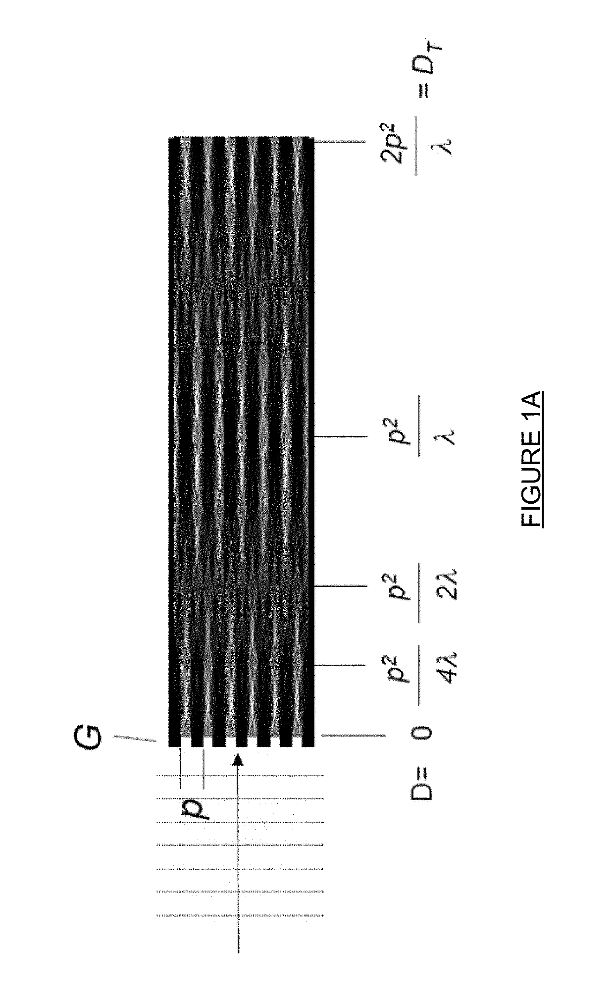
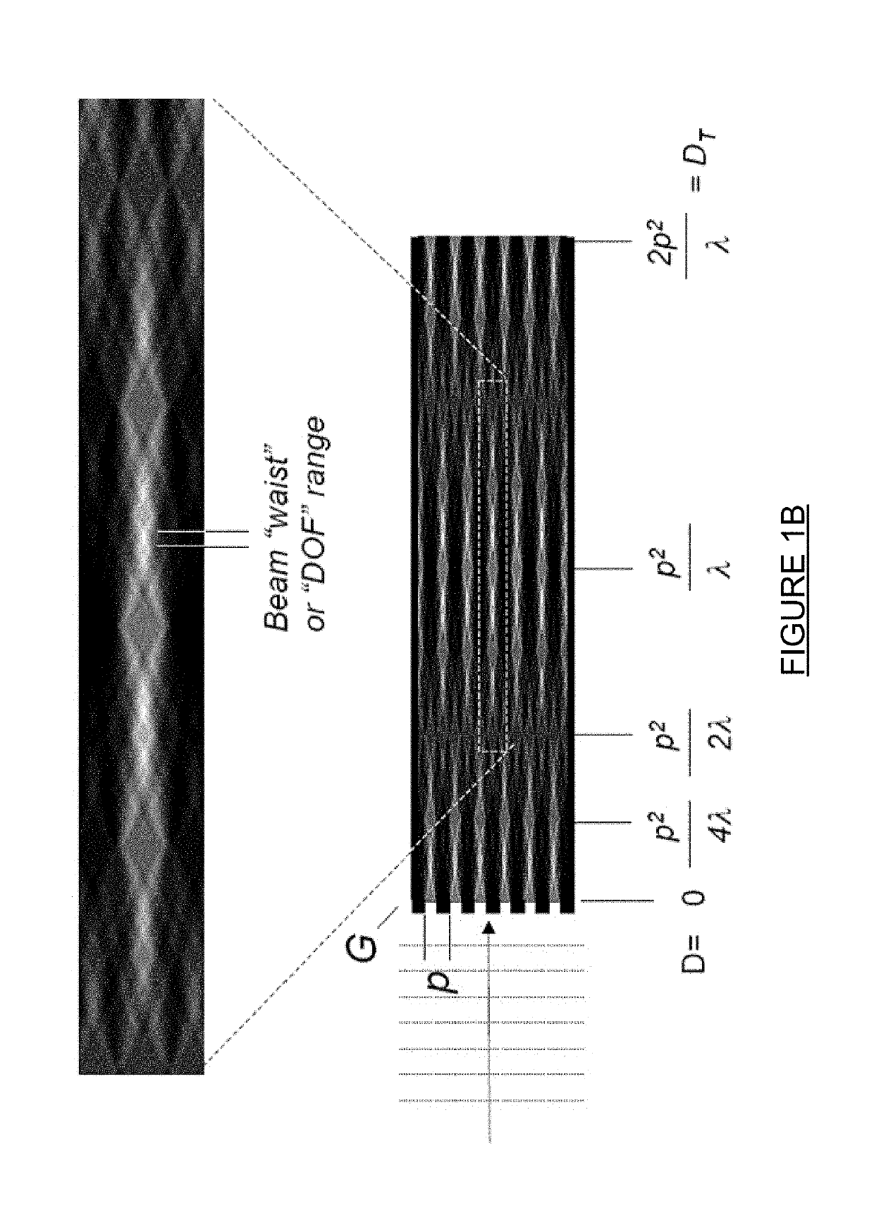
[0007]In embodiments, both the detector and the object are placed within the same waist or “depth-of-focus” range of a set of Talbot constructive fringes (anti-nodes). In some embodiments, the detector is placed downstream at any subsequent set of anti-nodes (an integer number of Talbot distances away). In some embodiments, the object is positioned on a mount that allows translation in the x- and y-directions perpendicular to the direction of x-ray beam propagation, allowing a “scanned” transmission image on a microscopic scale to be assembled. In some embodiments, the object is positioned on a mount that allows rotation about an axis perpendicular to the direction of x-ray beam propagation, allowing the collection of data on a microscopic scale to be used for laminographic or tomographic images reconstruction.
[0008]Additional masking layers may be inserted in the beam path to block a selected number of the micro-beams, allowing the use of detectors with larger pixel sizes for the remaining micro-beams. The use of a masking layer also allows the use of a detector with enhanced detection efficiency for the remaining micro-beams. Such masking layers may be placed in front of the object to be examined, between the object and the detector, or be designed as part of the detector structure itself.
Problems solved by technology
Prior art x-ray microscopes are generally limited by the resolution of the x-ray optics (e.g. zone plates) and / or the resolution of the pixel size of the detector.
Although some commercial x-ray microscope systems have a resolution of less than 100 nm, such systems have an extremely limited field of view, and high resolution x-ray microscopy with a large field of view has difficulty producing images with a resolution smaller than 1 micron.
Method used
Image
Click on the blue label to locate the original text in one second.
Reading with bidirectional positioning of images and text.
Examples
Embodiment Construction
[0034]This present technology includes systems for x-ray microscopy using an array of micro-beams having a micro- or nano-scale beam intensity profile to provide selective illumination of micro- or nano-scale regions of an object. Each micro-beam is separated from other micro-beams by regions of lower x-ray intensity, ranging from 0.8× to 0× of the intensity of the micro-beam. An array detector is positioned such that each pixel of the detector only detects x-rays corresponding to a single micro-beam, allowing the signal arising from the x-ray detector to be identified with the specific, limited micro- or nano-scale regions illuminated. In some instances, the object being imaged and the detector are positioned within the same Talbot diffraction order. In the present system, the spatial resolution is decoupled from the source size and the detector pixel size.
[0035]Imaging using Talbot fringes typically involves a grating (often a phase-shifting grating) to produce the Talbot interfer...
PUM
Property
Measurement
Unit
Talbot distance
aaaaa
aaaaa
energy
aaaaa
aaaaa
grating period
aaaaa
aaaaa
Abstract
Systems for x-ray microscopy using an array of micro-beams having a micro- or nano-scale beam intensity profile to provide selective illumination of micro- or nano-scale regions of an object. An array detector is positioned such that each pixel of the detector only detects x-rays corresponding to a single micro-or nano-beam. This allows the signal arising from each x-ray detector pixel to be identified with the specific, limited micro- or nano-scale region illuminated, allowing sampled transmission image of the object at a micro- or nano-scale to be generated while using a detector with pixels having a larger size and scale. Detectors with higher quantum efficiency may therefore be used, since the lateral resolution is provided solely by the dimensions of the micro- or nano-beams. The micro- or nano-scale beams may be generated using a arrayed x-ray source and a set of Talbot interference fringes.
Description
CROSS-REFERENCE TO RELATED APPLICATIONS[0001]This Patent Application claims the priority benefit of U.S. provisional patent application No. 62 / 485,916, titled “TALBOT X-RAY MICROSCOPE,” filed Apr. 15, 2017, and is a continuation-in-part of U.S. patent application Ser. No. 14 / 712,917, filed May 15, 2015 and entitled “X-RAY METHOD FOR MEASUREMENT, CHARACTERIZATION, AND ANALYSIS OF PERIODIC STRUCTURES”, which in turn is a continuation-in-part of U.S. patent application Ser. No. 14 / 700,137, filed Apr. 29, 2015 and entitled “X-RAY INTERFEROMETRIC IMAGING SYSTEM”, which in turn is a continuation-in-part of U.S. patent application Ser. No. 14 / 527,523, filed Oct. 29, 2014 and entitled “X-RAY INTERFEROMETRIC IMAGING SYSTEM”, which in turn claims the benefit of U.S. Provisional Patent Application Nos. 61 / 898,019, filed Oct. 31, 2013 and entitled “X-ray Phase Contrast imaging System”; 61 / 901,361, filed on Nov. 7, 2013 and entitled “An X-ray Source Consisting of an Array of Fine Sub-Sources”; a...
Claims
Application Information
Patent Timeline
Application Date:The date an application was filed.
Publication Date:The date a patent or application was officially published.
First Publication Date:The earliest publication date of a patent with the same application number.
Issue Date:Publication date of the patent grant document.
PCT Entry Date:The Entry date of PCT National Phase.
Estimated Expiry Date:The statutory expiry date of a patent right according to the Patent Law, and it is the longest term of protection that the patent right can achieve without the termination of the patent right due to other reasons(Term extension factor has been taken into account ).
Invalid Date:Actual expiry date is based on effective date or publication date of legal transaction data of invalid patent.

