Ultrasound transducer and method of manufacturing

a technology of ultrasound transducers and manufacturing methods, applied in the direction of mechanical vibration separation, semiconductor electrostatic transducers, instruments, etc., can solve the problems of difficult to obtain a thermal conductivity>0.3 w/mk for layers with low or otherwise specifiable characteristic acoustic impedance, and difficult to achieve a thermal conductivity of >0.3 w/mk for layers with low or otherwise specifiable characteristic acoustic impedance, and achieve low

Active Publication Date: 2019-06-04
SURF TECH AS
View PDF10 Cites 5 Cited by
  • Summary
  • Abstract
  • Description
  • Claims
  • Application Information

AI Technical Summary

Benefits of technology

[0011]The invention presents materials with fairly low acoustic impedance (˜1.5-5 MRayl) and high heat conductivity that are obtained by mixing polymer particles coated with a heat conducting layer in a polymer base material. The heat conducting layer on the particles can also be electrically isolating, making the composite material electrically isolating with good heat conductivity. The particles in the base material hence give a composite material where the thermal conductive material is utilized highly effectively. The result is a high heat conductivity where the characteristic acoustic impedance can be varied (optimized) by the changing the polymer core material type and the ratio of the polymer core and diameter to the thickness and material type of the coating layers. The heat conducting layer on the particles can be electrically conducting, making the material also electrically conducting that can have advantages in many situations, for example for electric shielding.

Problems solved by technology

The electro-acoustic transduction of the transducer arrays often has considerable power losses that produce heating of the transducer structure.
However, as these particles have high characteristic acoustic impedance, the use of such particles makes it difficult to obtain a thermal conductivity>0.3 W / mK for layers with low or otherwise specifiable characteristic acoustic impedance.
However, these ceramics are used as part of the composites of polymer and ferroelectric ceramic materials, where the thermal conductivity is limited by the polymer properties, and it is difficult to obtain a thermal conductivity above 0.3 W / mK for the composite material, as reported in the above publications.
That is, the added silver is very badly utilized, as the particle—particle contacts represents huge bottlenecks in the thermal transport.
Also, adding metal particles to the base often increases the acoustic impedance of the composite material to unwanted values.

Method used


Image

  • Ultrasound transducer and method of manufacturing
  • Ultrasound transducer and method of manufacturing
  • Ultrasound transducer and method of manufacturing

Examples


Embodiment Construction

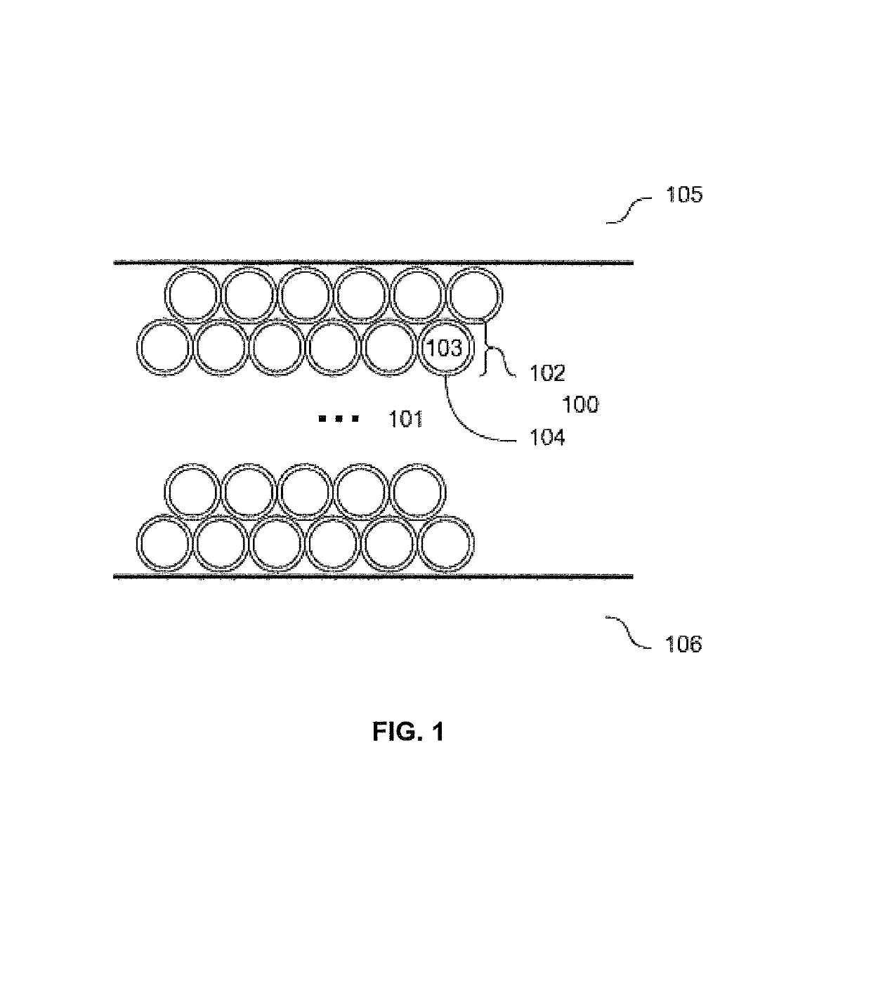
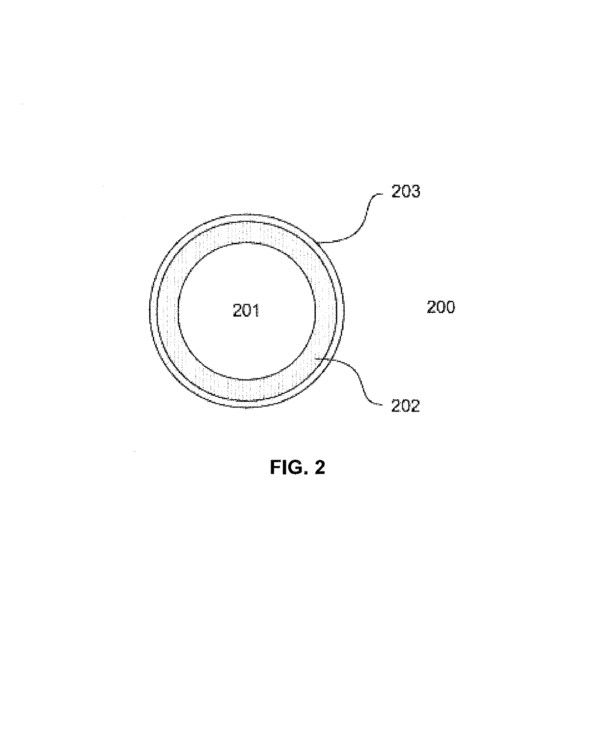
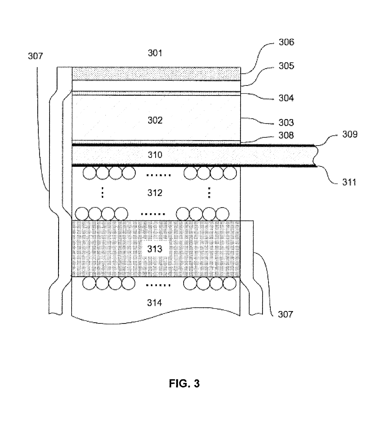
[0023]According to an embodiment there is provided an ultrasound transducer array probe arranged as a layered structure comprising at least one layer of transducer array elements and at least one further layer mounted in acoustic and thermal contact with said layer of transducer elements. The further layer is a composite material layer comprising a polymer base and particles. The particles in turn comprise a polymer core coated with a surface layer of a material that is more thermally conductive than the polymer core.

[0024]The thermal conductivity of surface layer is preferably at least 10 times the thermal conductivity of the polymer core.

[0025]An overall thermal conductivity of the further layer may be determined by selecting at least one of i) a type of materials for the particle surface layer, and ii) a thickness of the particle surface layer, and iii) a dimension of the particle polymer core, and iv) a fill density of said particles in the polymer base.

[0026]Additionally or alt...


PUM

PropertyMeasurementUnit
diametersaaaaaaaaaa
size distributionaaaaaaaaaa
porosityaaaaaaaaaa

Abstract

An ultrasound transducer array with at least one composite material layer. The layer having a polymer base in which polymer particles are embedded. The polymer particles are coated with a material that has a thermal conductivity that is higher than the thermal conductivity of the polymer base and the polymer particles.

Description

REFERENCE TO RELATED APPLICATION[0001]This application is a continuation of PCT application No. PCT / GB2014 / 053454 filed on Nov. 21, 2014, which claims priority from UK application No. 1320594.3 filed on Nov. 21, 2013, the entire contents of both being incorporated by reference herein.FIELD OF THE INVENTION[0002]The invention addresses design and manufacturing methods of ultrasound transducers for improved heat drainage from the array.DISCUSSION OF RELATED ART[0003]The electro-acoustic transduction of current ultrasound transducer arrays is based on one of:[0004]i) composites of polymers and ferroelectric ceramic materials, and[0005]ii) vibrating membranes on the surface of a substrate material, such as Si, where the electro-mechanical coupling is either capacitive (cmut) or through layers of piezoelectric material (pmut).[0006]To shape the bandwidth of the electro-acoustic transduction, and also for mechanical protection of the arrays, acoustic layers of polymer materials mixed with...

Claims


Application Information

Patent Timeline
Patent Type & Authority Patents(United States)
IPC IPC(8): G01S7/521B32B5/16B32B15/16G10K11/02B06B1/02
CPCG01S7/521B32B15/16G10K11/02B32B5/16B32B2307/302B06B1/02B32B2260/025B32B2260/046B32B2264/02B32B2264/105B32B2264/107B32B2264/12B32B2307/10B32B2307/20B32B2307/202B06B1/0607B06B1/0622B81B3/0081H04R19/005
Inventor ANGELSEN, BJORN A. J.
Owner SURF TECH AS
Why Eureka
Try Eureka