
System and method for vehicle occlusion detection

a vehicle occlusion and detection system technology, applied in the field of vehicle occlusion detection system and method, can solve the problems of autonomous vehicle object occlusion detection, inability to recover the shape of objects, and inability to deal with occluded object detection problems, etc., and achieve the effect of completely different relative purposes of current methods

Active Publication Date: 2019-06-04
TUSIMPLE INC
View PDF133 Cites 35 Cited by
  • Summary
  • Abstract
  • Description
  • Claims
  • Application Information

AI Technical Summary

Benefits of technology

This approach enables effective and efficient detection of occlusion status, providing valuable information for motion planning and driving inference generation, improving the safety and accuracy of autonomous vehicle operations by recognizing and handling occlusions in real-time.

Problems solved by technology

Object contour and occlusion detection is a fundamental problem for numerous vision tasks, including image segmentation, object detection, semantic instance segmentation, and occlusion reasoning.
Failure to detect an object (e.g., a car or a person) may lead to malfunction of the motion planning module of an autonomous driving car, thus resulting in a catastrophic accident.
As such, object occlusion detection for autonomous vehicles is an important safety issue.
Current object detection frameworks, although useful, cannot recover the shape of the object or deal with the occluded object detection problem.
However, the purpose of these current methods is totally different relative to the systems and methods described herein.
In other words, conventional systems and methods fail to recognize the importance of determining and using the occlusion status of vehicle objects detected in a set of input images.

Method used


Image

  • System and method for vehicle occlusion detection
  • System and method for vehicle occlusion detection
  • System and method for vehicle occlusion detection

Examples


Embodiment Construction

[0020]In the following description, for purposes of explanation, numerous specific details are set forth in order to provide a thorough understanding of the various embodiments. It will be evident, however, to one of ordinary skill in the art that the various embodiments may be practiced without these specific details.

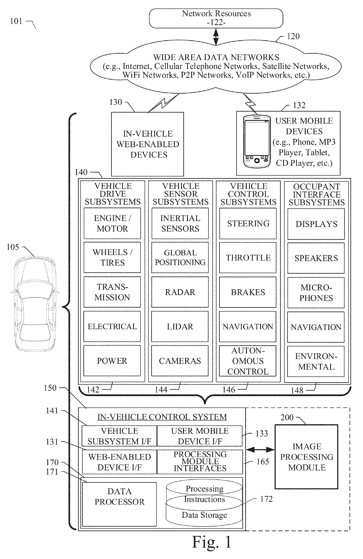
[0021]As described in various example embodiments, a system and method for vehicle occlusion detection are described herein. An example embodiment disclosed herein can be used in the context of an in-vehicle control system 150 in a vehicle ecosystem 101. In one example embodiment, an in-vehicle control system 150 with an image processing module 200 resident in a vehicle 105 can be configured like the architecture and ecosystem 101 illustrated in FIG. 1. However, it will be apparent to those of ordinary skill in the art that the image processing module 200 described and claimed herein can be implemented, configured, and used in a variety of other applications and system...


PUM


Abstract

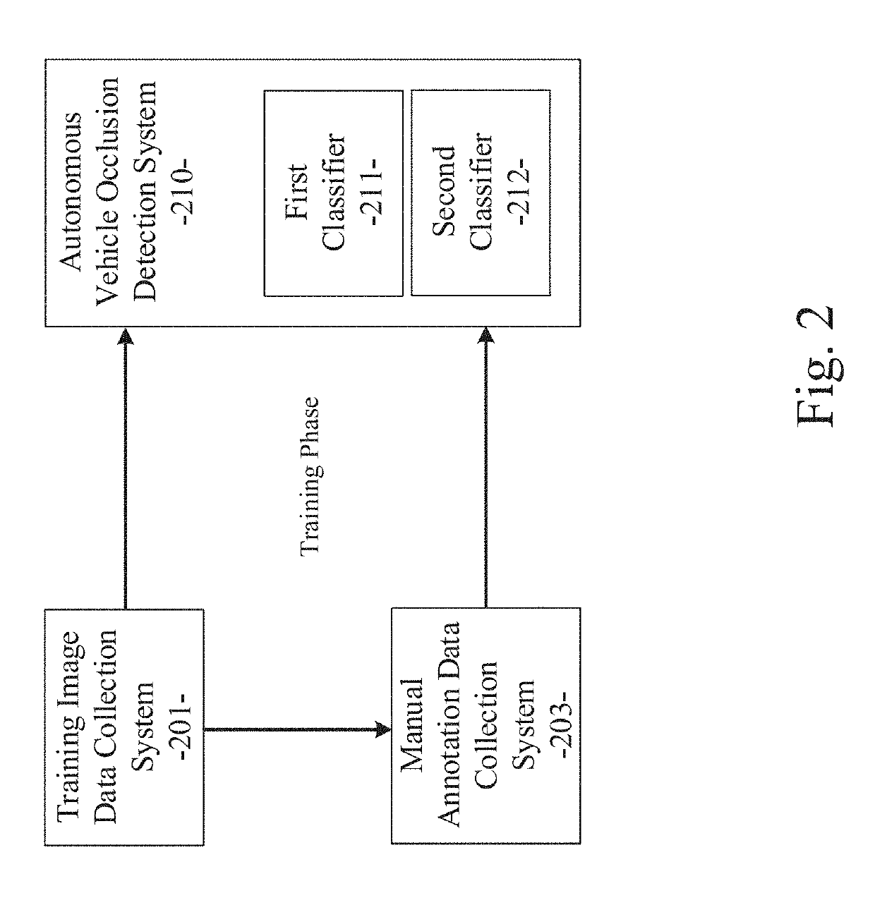
A system and method for vehicle occlusion detection is disclosed. A particular embodiment includes: receiving training image data from a training image data collection system; obtaining ground truth data corresponding to the training image data; performing a training phase to train a plurality of classifiers, a first classifier being trained for processing static images of the training image data, a second classifier being trained for processing image sequences of the training image data; receiving image data from an image data collection system associated with an autonomous vehicle; and performing an operational phase including performing feature extraction on the image data, determining a presence of an extracted feature instance in multiple image frames of the image data by tracing the extracted feature instance back to a previous plurality of N frames relative to a current frame, applying the first trained classifier to the extracted feature instance if the extracted feature instance cannot be determined to be present in multiple image frames of the image data, and applying the second trained classifier to the extracted feature instance if the extracted feature instance can be determined to be present in multiple image frames of the image data.

Description

PRIORITY PATENT APPLICATION[0001]This is a continuation-in-part (CIP) patent application drawing priority from U.S. non-provisional patent application Ser. No. 15 / 693,446; filed Aug. 31, 2017. This present non-provisional CIP patent application draws priority from the referenced patent application. The entire disclosure of the referenced patent application is considered part of the disclosure of the present application and is hereby incorporated by reference herein in its entirety.COPYRIGHT NOTICE[0002]A portion of the disclosure of this patent document contains material that is subject to copyright protection. The copyright owner has no objection to the facsimile reproduction by anyone of the patent document or the patent disclosure, as it appears in the U.S. Patent and Trademark Office patent files or records, but otherwise reserves all copyright rights whatsoever. The following notice applies to the disclosure herein and to the drawings that form a part of this document: Copyrigh...

Claims


Application Information

Patent Timeline
Patent Type & Authority Patents(United States)
IPC IPC(8): G06K9/00G06K9/62G05D1/02G06K9/20G06K9/46G06K9/78G06V10/44G06V10/764
CPCG06K9/00791G06K9/4604G06K9/6259G06K9/6267G06K9/78G05D1/0221G06K9/209G06V20/58G06V10/44G06V10/764G06F18/2413G06V20/56G06F18/24G06F18/2155
Inventor YU, HONGKAIYAN, ZHIPENGWANG, PANQUCHEN, PENGFEI
Owner TUSIMPLE INC
Learn More