
Multiple harvester planner

a harvester and planner technology, applied in the field of multi-use harvesters, can solve the problems of inefficiency in performing one or more agricultural functions, and insufficient space for a haul vehicle or a chaser cart, so as to improve the access to agricultural machines, the effect of improving the efficiency of harvesting and reducing the number of harvesters

Active Publication Date: 2019-06-11
AUTONOMOUS SOLUTIONS +1
View PDF18 Cites 2 Cited by
  • Summary
  • Abstract
  • Description
  • Claims
  • Application Information

AI Technical Summary

Benefits of technology

[0013]One advantage of the present invention is that it minimizes delays, interruptions, and inefficiencies by coordinating the movements and actions of multiple agricultural machines and servicing vehicles within the headlands or lands of a field. Another advantage is that it improves access to the agricultural machines by the servicing vehicles for coordinated activities such as unloading on the go. Still another advantage is that the present invention is robust in regards to variations in timing, vehicle configurations, and field arrangements and conditions.

Problems solved by technology

This being the case, it is not uncommon for there to be delays, interruptions, and inefficiencies in performing the one or more agricultural functions.
Because multiple combines are in the field, such that there is not wide open space on one side of the combine as would be the case with a single combine operation, there may be insufficient space for a haul vehicle or chaser cart to approach the combine, receive the harvested crop, and turn around to exit the field.
Further, there may not be space for the combine itself to turn away in order to approach the haul vehicle or chaser cart.
As a result, the combine that requires unloading may have to wait until sufficient space has been cleared of crops by another combine, or may have to back entirely out of its row, in order to unload.
Alternately, there may be sufficient space alongside each of the combines in the field for unloading, but the combines may be working at some distance from each other, so that the haul vehicles or chaser carts must travel between combines, resulting in inefficient use of time and fuel.

Method used


Image

  • Multiple harvester planner
  • Multiple harvester planner

Examples


Embodiment Construction

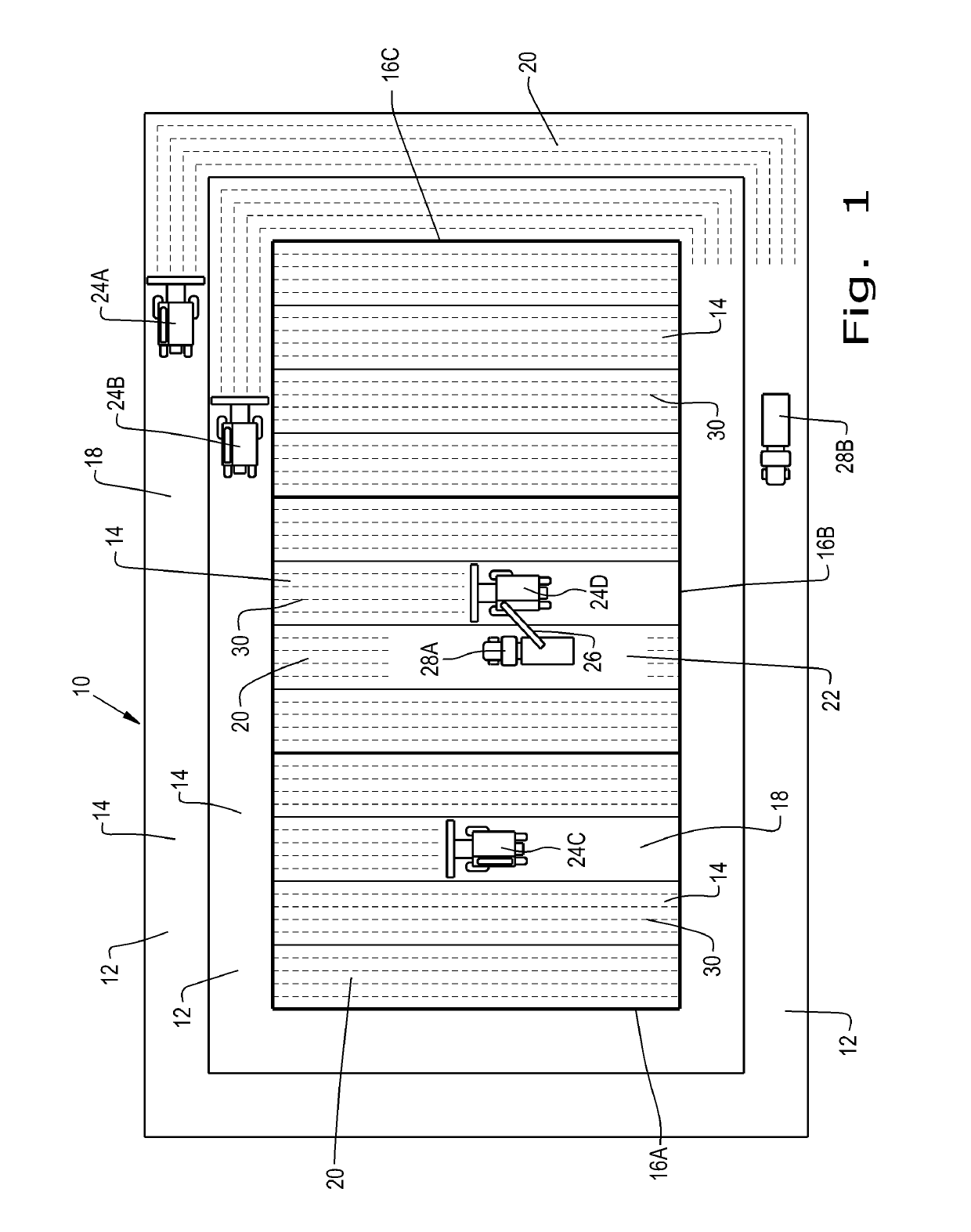
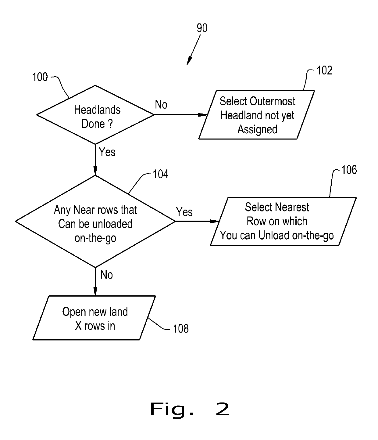
[0019]Referring now to the drawings, and more particularly to FIG. 1, there is shown a field 10 being harvested using multiple agricultural machines in the form of combines 24A, 24B, 24C, and 24D. The multiple agricultural machines perform a primary agricultural function upon the field 10, in the case of combines 24A, 24B, 24C, and 24D, the primary agricultural function being harvesting a crop. Service vehicles in the form of haul vehicle or chaser carts 28A and 28B perform service functions in connection with the multiple agricultural machines, in the case of haul vehicle or chaser carts 28A and 28B, the service function being unloading the combines 24A, 24B, 24C, and 24D as needed by way of an unloading system 26 that is part of each combine 24A, 24B, 24C, and 24D. Each of the combines 24A, 24B, 24C, and 24D and the haul vehicle or chaser carts 28A and 28B receives direction from a planner or dispatch algorithm 90 (not shown in FIG. 1). The planner or dispatch algorithm 90 may run...


PUM


Abstract

A system has an algorithm for organizing the actions of agricultural machines and servicing vehicles in a field. The algorithm divides the field into logical chunks of work, including at least one swath within at least one headland and within at least one land, which it then assigns to the agricultural machines in order. Priority is first given to working the headlands, then to working swaths within lands where an agricultural machine can perform its function while remaining accessible to the servicing vehicles. When the agricultural machine is in an area where it is not accessible to a servicing vehicle and needs service, the agricultural machine creates an impromptu servicing area. This may be an area within a swath that the agricultural machine has cleared of crops in order to provide the servicing vehicle, such as a haul vehicle or grain cart, access to the agricultural machine and space to turn around.

Description

BACKGROUND OF THE INVENTION1. Field of the Invention[0001]The present invention relates to agricultural machines such as combines, forage harvesters, windrowers, harvesting machines, crop preparation machines, tractors, and implements, and, more particularly, to agricultural machines that perform one or more agricultural functions in a field wherein multiple such agricultural machines operate in coordination to perform the one or more agricultural functions.2. Description of the Related Art[0002]An agricultural harvester known as a “combine” is historically termed such because it combines multiple harvesting functions with a single harvesting unit, such as picking, threshing, separating and cleaning. A combine removes the crop from a field, and performs a threshing operation on the crop to remove the grain, cleans it using a cleaning system, and temporarily stores it in an onboard grain tank. Non-grain crop material such as straw, chaff, and other debris is chopped and discharged ou...

Claims


Application Information

Patent Timeline
Patent Type & Authority Patents(United States)
IPC IPC(8): A01B79/00G06Q50/02G06Q10/06
CPCA01B79/005G06Q50/02G06Q10/0633
Inventor TURPIN, BRET T.MORWOOD, DANIEL J.FOSTER, CHRISTOPHER ALAN
Owner AUTONOMOUS SOLUTIONS
Learn More