Duct flange structure, and manufacturing method for the same
a technology of duct flange and manufacturing method, which is applied in the direction of ducting arrangement, lighting and heating apparatus, heating types, etc., can solve the problems of increasing the cost of duct components, requiring welding or coating work, and a large amount of cost and labor for manufacturing ducts, so as to reduce labor and time, short time, and improve the appearance of external appearance
- Summary
- Abstract
- Description
- Claims
- Application Information
AI Technical Summary
Benefits of technology
Problems solved by technology
Method used
Image
Examples
first embodiment
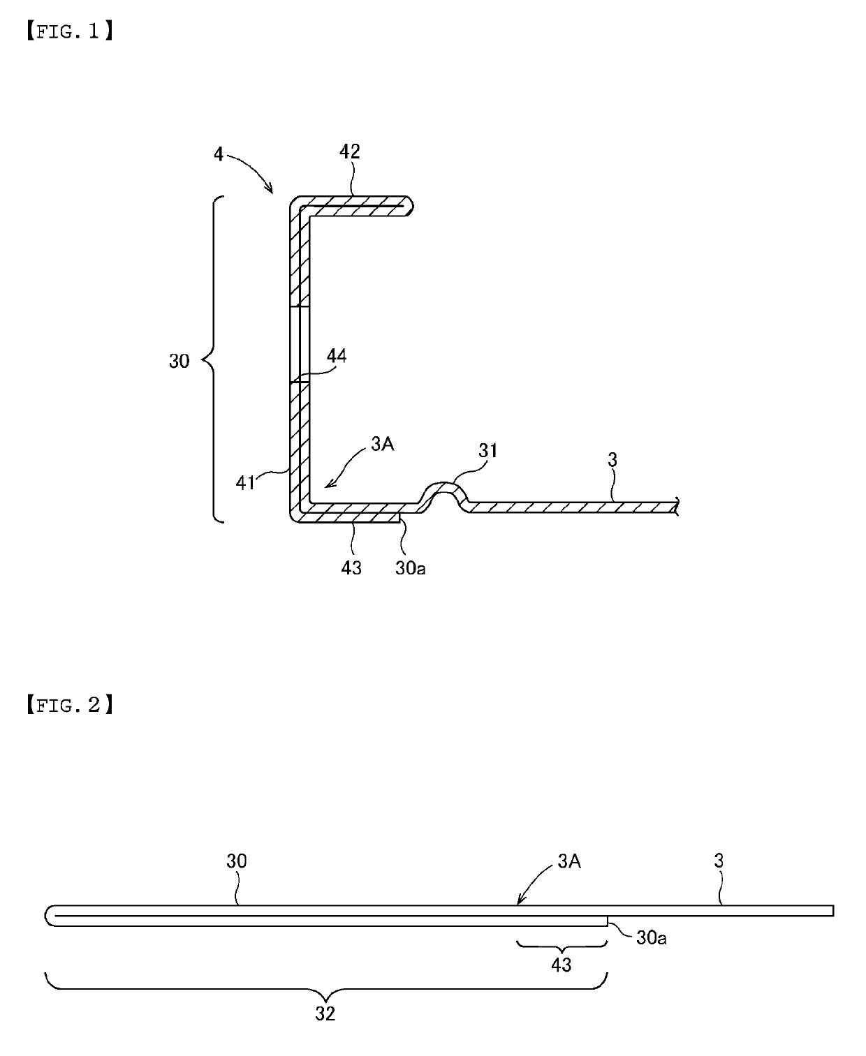
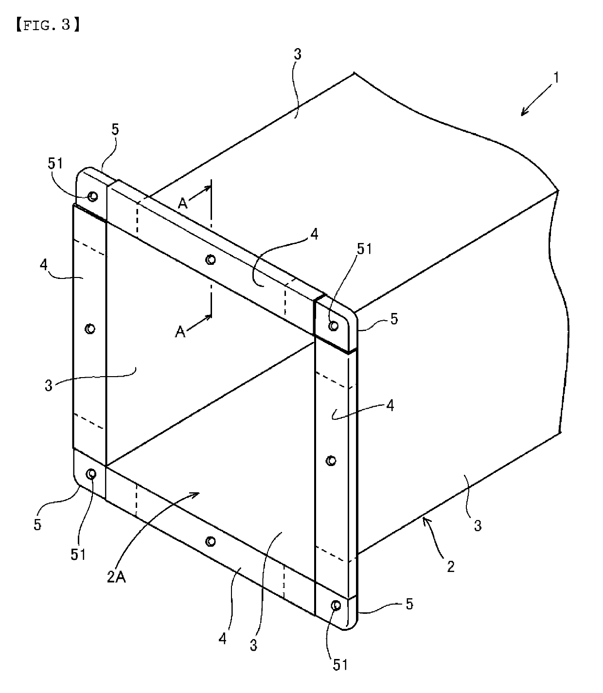
[0038]FIGS. 1 to 3 show a first embodiment of the present invention. FIG. 3 is a perspective view of a duct 1 provided with a duct flange structure according to this embodiment. The duct flange structure is a flange structure which is arranged in an opening end portion 2A of a duct body 2 and which connects the duct 1 to another duct or the like. FIG. 1 shows a close-up cross-sectional view of one plate 3, which is also herein interchangeably referred to as a “plate portion,” of the duct body 2 (FIG. 3), including a formed example extension portion 30. As shown in FIG. 3, the duct body may include four of the aforementioned plate portion(s) 3 intersecting one one-another and forming duct body 2.
[0039]The duct body 2 has a duct body having a substantially quadrilateral shape in section and is constituted by four wall plates 3 each of which is a corrosion-resisting steel plate. Specifically, the duct body 2 is formed by arranging the substantially rectangular wall plates 3 in a quadri...
second embodiment
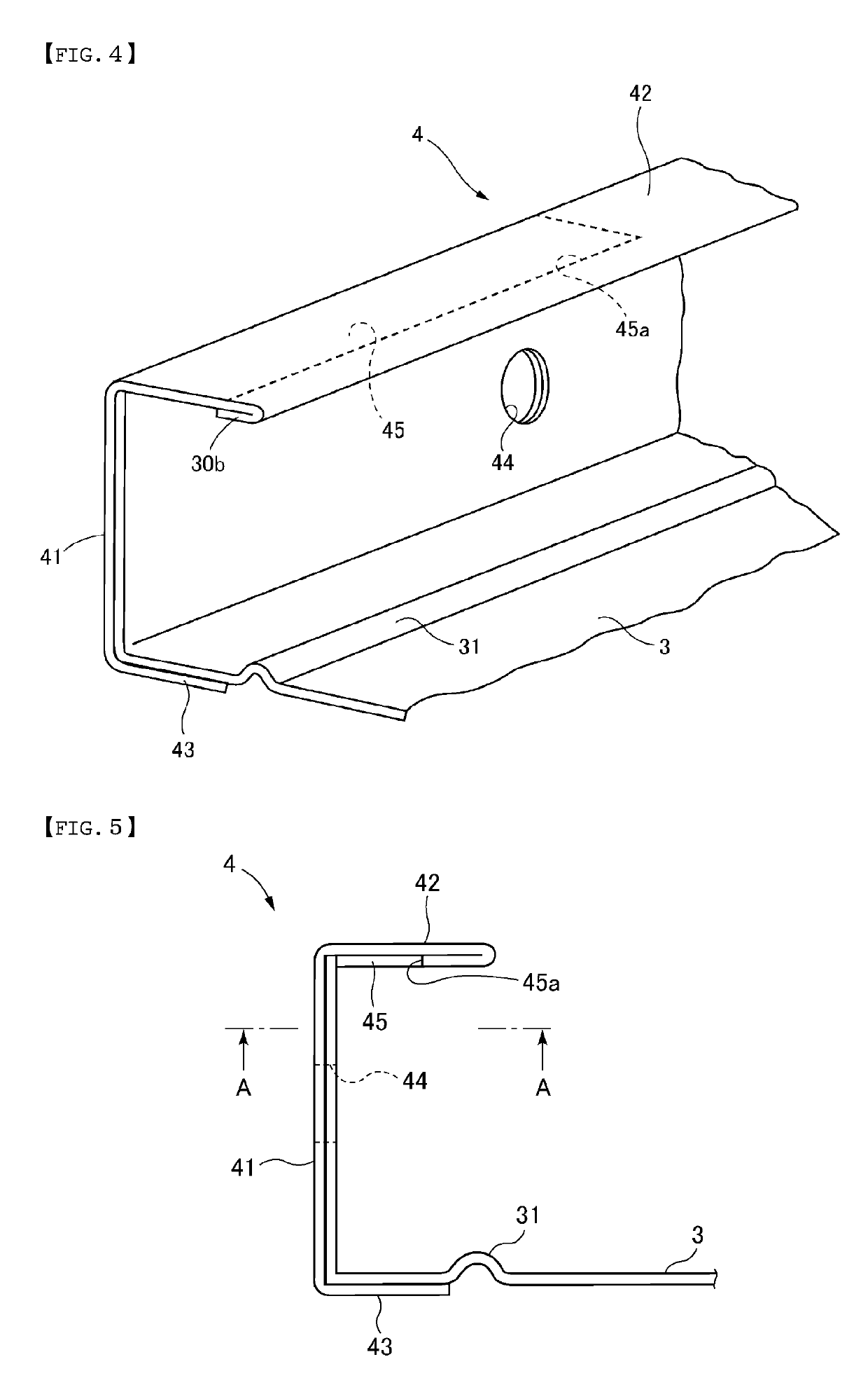
[0055]FIGS. 4 to 11 show a second embodiment of the present invention. FIG. 4 is a perspective view of a portion of a duct flange structure according to this embodiment. The embodiment is different from the first embodiment in the respect that the horizontal portion 42 is formed with a cutout portion 45. The other component elements of the second embodiment are given the same reference characters and numerals as those of the first embodiment, as long as the former are identical to the latter. Thus, their description is omitted.
[0056]In the flange portion 4 of this embodiment, the extension portion 30 is formed with the cutout, portion 45 located inside of the horizontal portion 42 and extending from a side edge 30b, which is also herein interchangeably referred to as a “second extending flange portion.” One edge 521 of an attachment portion 52 of the corner piece 5, which is also interchangeably referred to herein as a “reinforcing corner piece,” is attached and fixed to the cutout ...
PUM
| Property | Measurement | Unit |
|---|---|---|
| shape | aaaaa | aaaaa |
| pressure | aaaaa | aaaaa |
| strength | aaaaa | aaaaa |
Abstract
Description
Claims
Application Information
 - R&D
- Intellectual Property
- Life Sciences
- Materials
- Tech Scout
- Unparalleled Data Quality
- Higher Quality Content
- 60% Fewer Hallucinations
Browse by: Latest US Patents, China's latest patents, Technical Efficacy Thesaurus, Application Domain, Technology Topic, Popular Technical Reports.
© 2025 PatSnap. All rights reserved.Legal|Privacy policy|Modern Slavery Act Transparency Statement|Sitemap|About US| Contact US: help@patsnap.com


