Wind turbine blade with improved fibre transition

a technology of fibre transition and wind turbine blade, which is applied in the field of wind turbine blade with improved fibre transition, can solve the problems of air pockets, difficult or impossible to remove, and ensure the complete distribution of polymer in the entire mould cavity, so as to improve mechanical bonding and increase bonding

Active Publication Date: 2019-06-25
LM WP PATENT HLDG
View PDF20 Cites 4 Cited by
  • Summary
  • Abstract
  • Description
  • Claims
  • Application Information

AI Technical Summary

Benefits of technology

[0022]Accordingly, it is seen that the gradual transition is provided by a combined double-tapered thickness section with first type reinforcement fibres sandwiched between second type reinforcement fibres or vice versa. Although this increases the complexity of the fibre layup procedure, this embodiment provides a stronger stiffness transition of the wind turbine component between the two fibre types, and further the transition may be shorter than prior art wind turbine components having a single taper section. Further, it is clear that the double-tapering is provided during layup and that the reinforcement material is impregnated with a polymer resin and then cured or hardened so that the two types of reinforcement fibres are embedded in a common polymer matrix. This has the advantage of lowering stress concentrations and in particular the energy release rate at the common boundary between the two types of fibre, especially compared to parts joined at a bond line.
[0081]Preferably, the method comprises the step of treating a surface of said at least a portion of said cured blade element prior to said step of laying up said secondary fibre material, wherein said step of treating acts to increase the bonding between said reinforced section and said cured blade element after said step of curing said secondary resin. This may improve the mechanical bonding between the two parts.

Problems solved by technology

Ensuring a complete distribution of the polymer in the entire mould cavity is, however, often difficult, and accordingly this often results in so-called dry spots, i.e. areas with fibre material not being sufficiently impregnated with resin.
Thus dry spots are areas where the fibre material is not impregnated, and where there can be air pockets, which are difficult or impossible to remove by controlling the vacuum pressure and a possible overpressure at the inlet side.
This is a time-consuming and tiresome process.
This is not desirable, especially not when the polymer has not hardened, as it can result in deformations in the inserted fibre material and thus in a local weakening of the structure, which can cause for instance buckling effects.
Furthermore the infusion process has become more complicated, as the impregnation of large shell members, such as blades, requires control of the flow fronts to avoid dry spots, said control may e.g. include a time-related control of inlet channels and vacuum channels.
This increases the time required for drawing in or injecting polymer.
As a result the polymer has to stay liquid for a longer time, normally also resulting in an increase in the curing time.
The disadvantage with prepregs is that the material cost is higher than for non-impregnated fibres.
However, it has been found that such a transition is not mechanically strong.
One drawback of such a solution is, however, increased weight due to the increased use of fibres, e.g. glass fibres, in the transition area between glass fibres and carbon fibres.

Method used


Image

  • Wind turbine blade with improved fibre transition
  • Wind turbine blade with improved fibre transition
  • Wind turbine blade with improved fibre transition

Examples


Embodiment Construction

[0092]Embodiments of the invention are described below, by way of example, with reference to the accompanying drawings, in which:

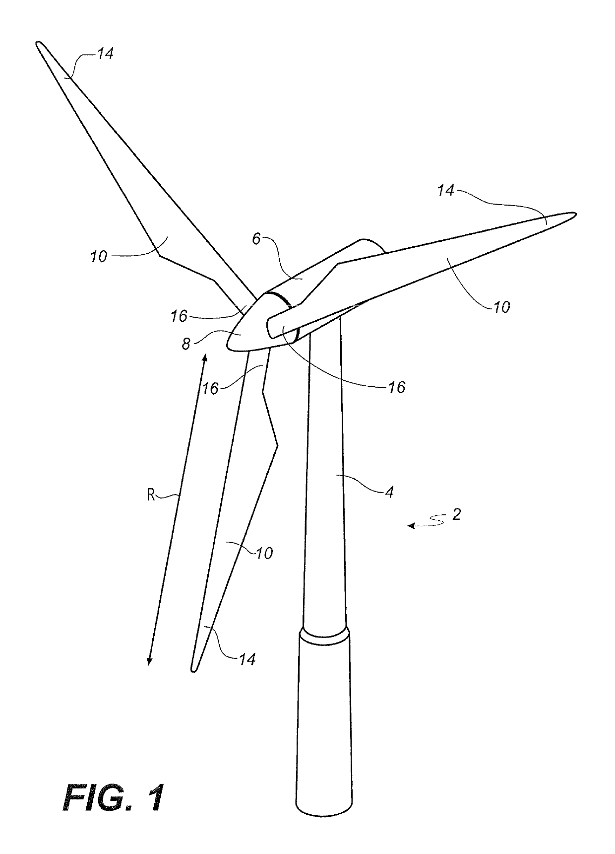
[0093]FIG. 1 shows a wind turbine,

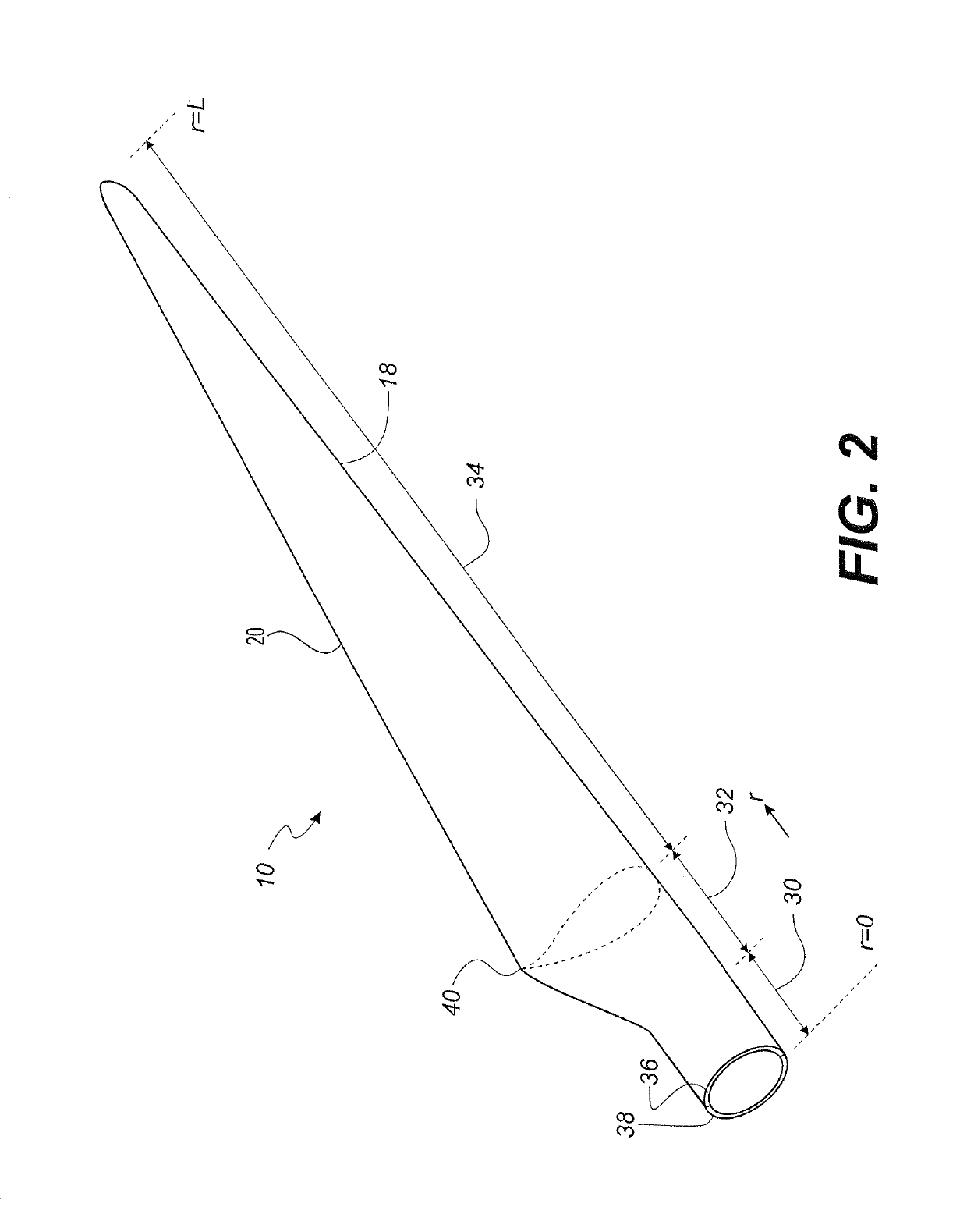
[0094]FIG. 2 shows a schematic view of a wind turbine blade according to the invention,

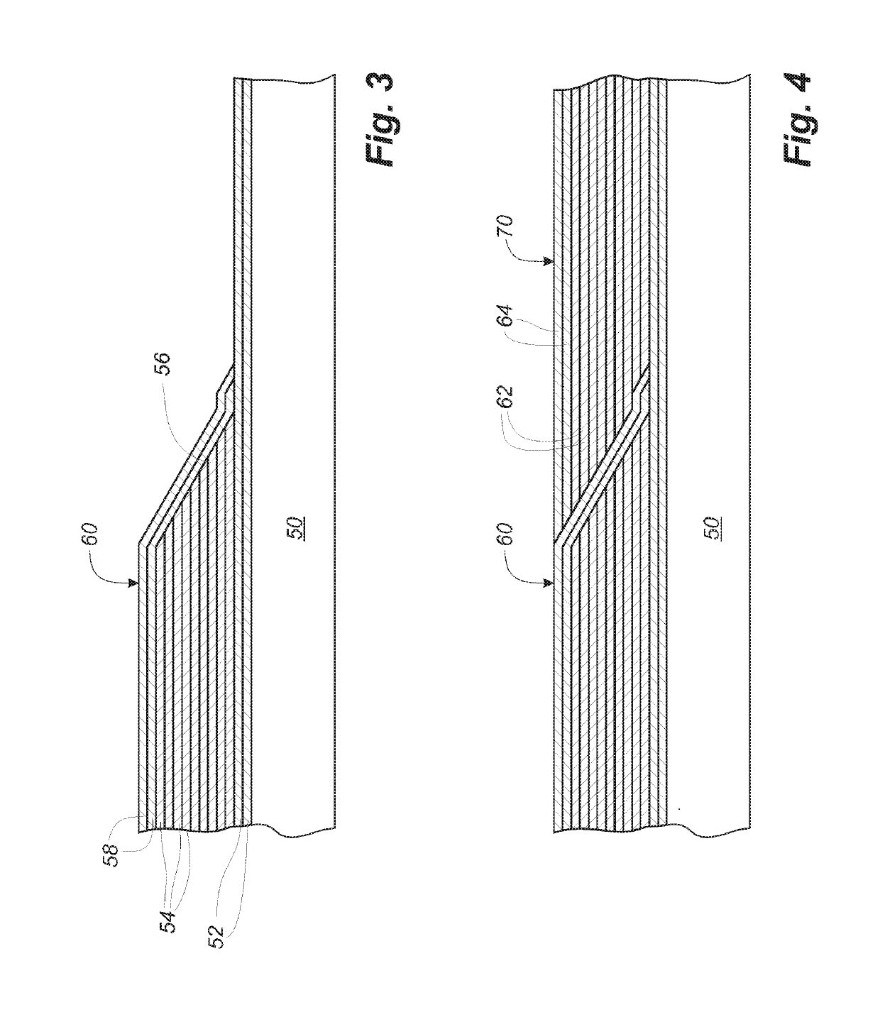
[0095]FIG. 3 shows the layup of fibre material for forming a cured blade element,

[0096]FIG. 4 shows the layup of fibre material for forming an integrated reinforced section on the cured blade element of FIG. 3,

[0097]FIG. 5 shows a cross section of the cured blade element and integrated reinforced section,

[0098]FIG. 6 shows a schematic view of a blade shell part comprising the cured blade element and integrated reinforced section,

[0099]FIG. 7 shows a schematic view of a the fibre layup of a first thickness section of a blade component,

[0100]FIG. 8 shows a schematic view of a the fibre layup of a second thickness section of a blade component, and

[0101]FIGS. 9a-d show different variations of embodiments according to the invention.

[0102]FIG....


PUM

PropertyMeasurementUnit
lengthaaaaaaaaaa
lengthaaaaaaaaaa
elastic modulusaaaaaaaaaa

Abstract

A wind turbine blade having a transition between two reinforcement fiber types is described. A gradual transition is provided by a combined double-tapered thickness section with a first type of reinforcement fibers sandwiched between a second type of reinforcement fibers or vice versa. The double-tapering is provided during layup and the reinforcement material is impregnated with a polymer resin and then cured or hardened so that the two types of reinforcement fibers are embedded in a common polymer matrix.

Description

[0001]This is a National Phase Application filed under 35 U.S.C. 371 as a national stage of PCT / EP2015 / 051951, filed Jan. 30, 2015, an application claiming the benefit from the European patent Application No. 14153439.6, filed Jan. 31, 2014, the content of each of which is hereby incorporated by reference in its entirety.FIELD OF THE INVENTION[0002]The present invention relates to a method of manufacturing a wind turbine blade and intermediate products of a wind turbine blade. The invention further relates to a wind turbine blade and intermediate products of the wind turbine blade.BACKGROUND OF THE INVENTION[0003]Wind turbine blades are often manufactured according to one of two constructional designs, namely a design where a thin aerodynamic shell is glued onto a spar beam, or a design where spar caps, also called main laminates, are integrated into the aerodynamic shell.[0004]In the first design, the spar beam constitutes the load bearing structure of the blade. The spar beam as w...

Claims


Application Information

Patent Timeline
Patent Type & Authority Patents(United States)
IPC IPC(8): F03D1/06B29C70/08B29D99/00B29C70/30B29K31/00B29K63/00B29K309/08B29L31/08
CPCF03D1/0675B29C70/30B29D99/0025B29C70/08Y02P70/523B29K2031/00B29K2063/00B29K2309/08B29K2995/0046B29L2031/085F05B2220/30F05B2230/20F05B2240/2211F05B2280/5001F05B2280/6003Y02E10/721Y02E10/72Y02P70/50B29C70/304
Inventor JORGENSEN, JEPPE BJORNKILDEGAARD, CASPERJESPERSEN, KLAVS
Owner LM WP PATENT HLDG
Why Eureka
Try Eureka