Linear bi-stable compliant crank-slider-mechanism

a crankshaft and crank-slider technology, applied in the field of surface, can solve the problems of reducing the assembly time, affecting the performance and cost of the mechanical joints, and affecting the cos

Active Publication Date: 2019-06-25
UNIV OF SOUTH FLORIDA
View PDF8 Cites 4 Cited by
  • Summary
  • Abstract
  • Description
  • Claims
  • Application Information

AI Technical Summary

Problems solved by technology

The absence or reduction of mechanical joints impacts both performance and cost.
Moreover, cost is also affected by reduced assembly time and, in most cases, due to its hingeless design, the fabrication of such mechanisms can be produced from a single piece.
The chief criticisms of this approach are that the models are approximate and have limited, albeit known, accuracy.
Moreover, the identification between flexure geometries and rigid-body mechanisms has been limited to a small but versatile set of planar configurations.
This approach has been successful, but has also been criticized for producing results identical to those produced more quickly by the PRBM approach, or results that are not physically realizable.
As a general rule, this approach is more capable and accurate than the PRBM approach, but also more time consuming.
This approach uses flexures much smaller than the overall mechanism size, so it is not generally applicable to millimeter-scale and smaller mechanisms.
These techniques are important but do not have a direct bearing on the claimed subject matter disclosed herein.
His result means that spheres cannot be made into planes without crumpling or tearing or stretching (distorting) the surface.
This fundamental geometric limitation makes the building of certain types of curved surfaces (those with two non-zero principal curvatures) intrinsically more difficult than working with planar surfaces (both principal curvatures equal to zero) or developable surfaces (one principal curvature equal to zero).
Such containers are designed for large volumes, however, when not in use, may become cumbersome.
Conventional methods for constructing these barriers can be costly, but even when they are inexpensive, the numbers of these kinds of objects mean that they represent a significant economic investment.
Such barriers often incur additional costs when they require modification or removal.

Method used


Image

  • Linear bi-stable compliant crank-slider-mechanism
  • Linear bi-stable compliant crank-slider-mechanism
  • Linear bi-stable compliant crank-slider-mechanism

Examples


example 1

A. The First Approach

[0243]i. Using the LBCCSM Model

[0244]Design statement: A linear bi-stable mechanism is to be designed. The distance between the two stable points is 25.2 mm, and the mechanism should fit in an area of 43.8 mm by 21 mm. The mechanism is laser cut from a 5 mm thick Polypropylene sheet with design safety factor of 1.

[0245]Design inputs: Δ=25.2 mm, X=43.8 mm, bmax=21 mm, t=5 mm, SF=1. γ=ρ=0.85 and KΘ=2.65 from the PRBM.

[0246]Design Solution:[0247]Step 1: Δ=25.2 mm and X=43.8 mm.[0248]Step 2: From table 1, θ1=30° for low footprint.[0249]Step 3: Using eq. (32), L1=36.03 mm.[0250]Step 4: Using eq. (33), L2=22 mm[0251]Step 5: Using eq. (34), θ2i=55°.[0252]Step 6a: From inputs, bmax / X=0.48, bi=18 mm.[0253]Step 6b: Using FIG. 7A, v=25.[0254]Step 7: Using FIG. 9A, Θ1=7°.[0255]Step 8: Material: Polypropylene, E=1.35 GPa, σy=35 MPa,[0256]Using eq. (35), w1=3.39 mm.[0257]Step 9: Using eq. (16), m=0.61,[0258]Using eq. (36), w1=0.78 mm.[0259]Step 10: Using FIG. 9A, f=0.04.[026...

example 2

B. The Second Approach

[0268]i. Using the LBCCSM Model

[0269]Design statement: A linear bi-stable mechanism needs to be designed. The distance between the two stable points is 55 mm and the mechanism should fit in a length of 70 mm. The actuator that would be used has a maximum force output of 2 N. The mechanism is laser cut from a 7 mm thick Polypropylene sheet with design safety factor of 1.5.

[0270]Design inputs: Δ=55 mm, X=70 mm, Fmax=2 N, t=7 mm, SF=1.5, γ=ρ=0.85 and KΘ=2.65 from the PRBM.

[0271]Design solution:[0272]Step 1: Δ=55 mm and X=70 mm.[0273]Step 2: From table 1, θ1=50° for intermediate footprint.[0274]Step 3: Using eq. (32), L1=66.12 mm.[0275]Step 4: Using eq. (33), L2=57.63 mm[0276]Step 5: Using eq. (34), θ2i=61.5°.[0277]Step 6a: Using eq. (38), J=0.62.[0278]Step 6b: Using FIG. 11A, v=16.[0279]Step 7: Using FIG. 8B, Θ1=6.52°.[0280]Step 8: Material: Polypropylene, E=1.35 GPa, σy=35 MPa, Using eq. (35), w1=4.45 mm.[0281]Step 9: Using eq. (16), m=0.87, Using eq. (36), w1=1...


PUM


Abstract

A linear element with two stable points, it can be used as trust element allows for change in length. It can transform structure from one shape to another thus allowing for morphable configuration. A new model is presented herein for a linear bi-stable compliant mechanism and design guidelines for its use. The mechanism is based on the crank-slider mechanism. This model takes into account the first mode of buckling and post-buckling behavior of a compliant segment to describe the mechanism's bi-stable behavior. The kinetic and kinematic equations, derived from the Pseudo-Rigid-Body Model, were solved numerically and are represented in plots. This representation allows the generation of step-by-step design guidelines. Because different applications may have different input requirements, two different design approaches are described herein with different parameters subsets as inputs.

Description

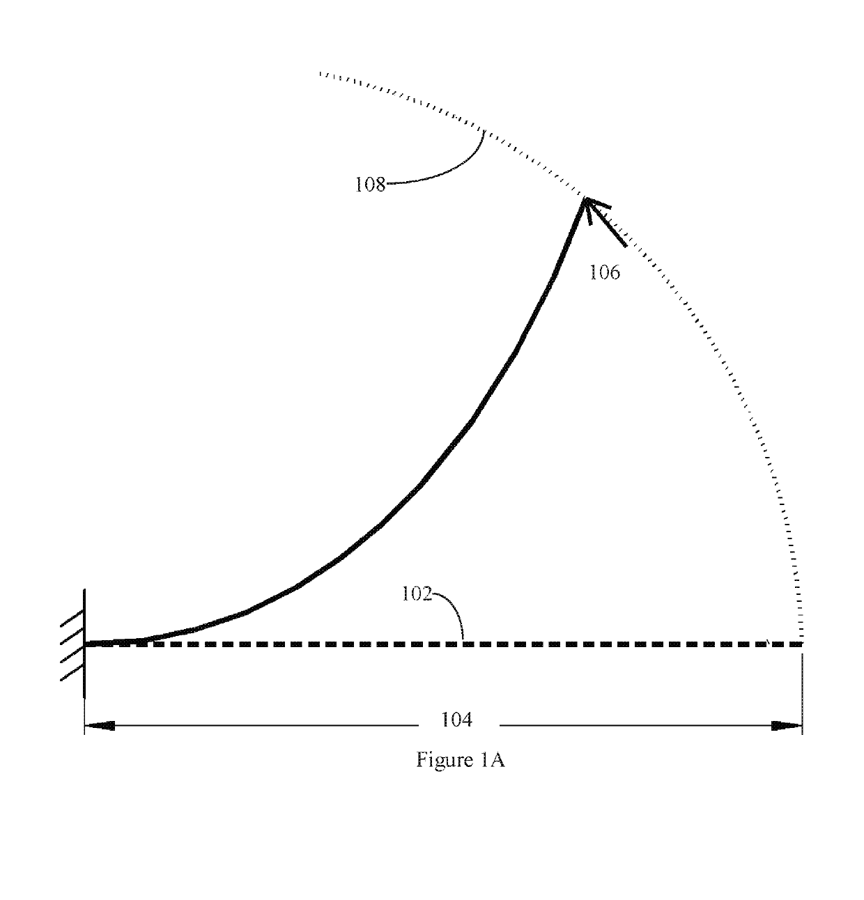
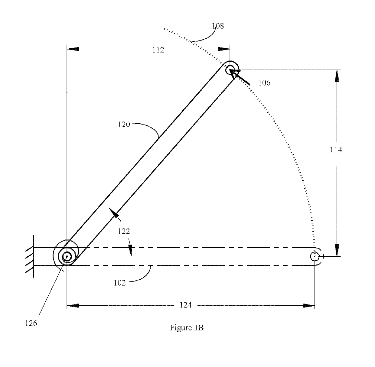
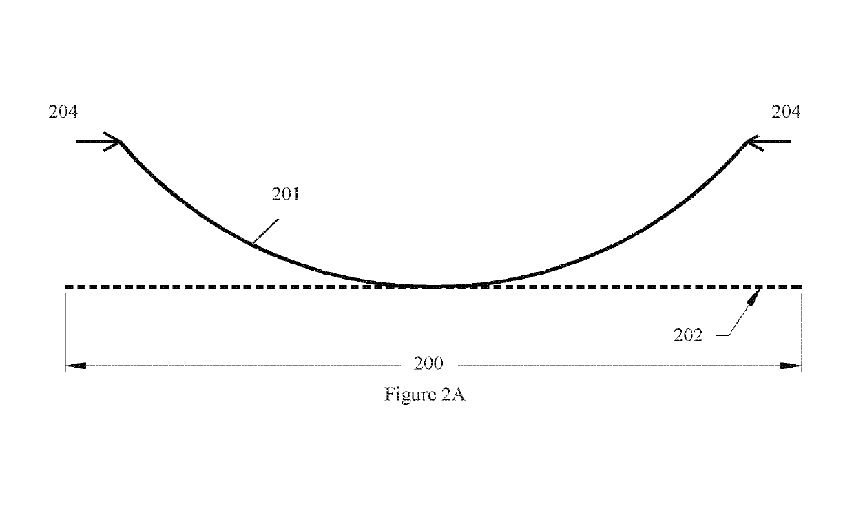
CROSS-REFERENCE TO RELATED APPLICATIONS[0001]This nonprovisional application is a divisional of and claims priority to U.S. Nonprovisional patent application Ser. No. 15 / 198,627, entitled “Linear Bi-Stable Compliant Crank-Slider-Mechanism,” filed Jun. 30, 2016 by the same inventors, which is a continuation of and claims priority to U.S. Provisional Patent Application No. 62 / 199,606, entitled “Linear Bi-Stable Compliant Crank-Slider-Mechanism (LBCCSM),” filed Jul. 31, 2015 by the same inventors, the entirety of each application are incorporated herein by reference.FEDERALLY SPONSORED RESEARCH OR DEVELOPMENT[0002]This invention was made with Government support under Grant No. CMMI-1053956 awarded by the National Science Foundation. The government has certain rights in the invention.BACKGROUND1. Field of the Invention[0003]The claimed subject matter relates, generally, to surfaces, the shape of which can be changed in response to externally applied forces. More specifically, it relates...

Claims


Application Information

Patent Timeline
Patent Type & Authority Patents(United States)
IPC IPC(8): F16C11/12F16C7/06
CPCF16C7/06F16C11/12F16H21/18
Inventor ALQASIMI, AHMADLUSK, CRAIG
Owner UNIV OF SOUTH FLORIDA
Why Eureka
Try Eureka