Luminous keyboard

a keyboard and light-emitting technology, applied in the field of keys, can solve the problems of inconvenience in use, difficulty for users to recognize the character symbol of the key cap, and the inability to effectively spread the light emitted from the led to the entire key cap, so as to improve the recognizability of the character symbol of each key cap

Inactive Publication Date: 2019-06-25
PRIMAX ELECTRONICS LTD
View PDF6 Cites 1 Cited by
  • Summary
  • Abstract
  • Description
  • Claims
  • Application Information

AI Technical Summary

Benefits of technology

[0005]A main objective of the present invention is to provide a luminous keyboard, including a light emitting module capable of adjusting an irradiation range according to character symbols of different key caps, so as to improve recognizability of a character symbol of each key cap.

Problems solved by technology

However, when an LED is at a short distance from a key cap, because light rays emitted from the LED are excessively concentrated, the light rays emitted from the LED cannot be effectively spread to the entire key cap.
Further, if light rays emitted from an LED are excessively strong, a notable bright spot may be generated on a surface of a key cap, making it difficult for a user to recognize a character symbol of the key cap, leading to inconvenience in use.

Method used


Image

  • Luminous keyboard
  • Luminous keyboard
  • Luminous keyboard

Examples


first embodiment

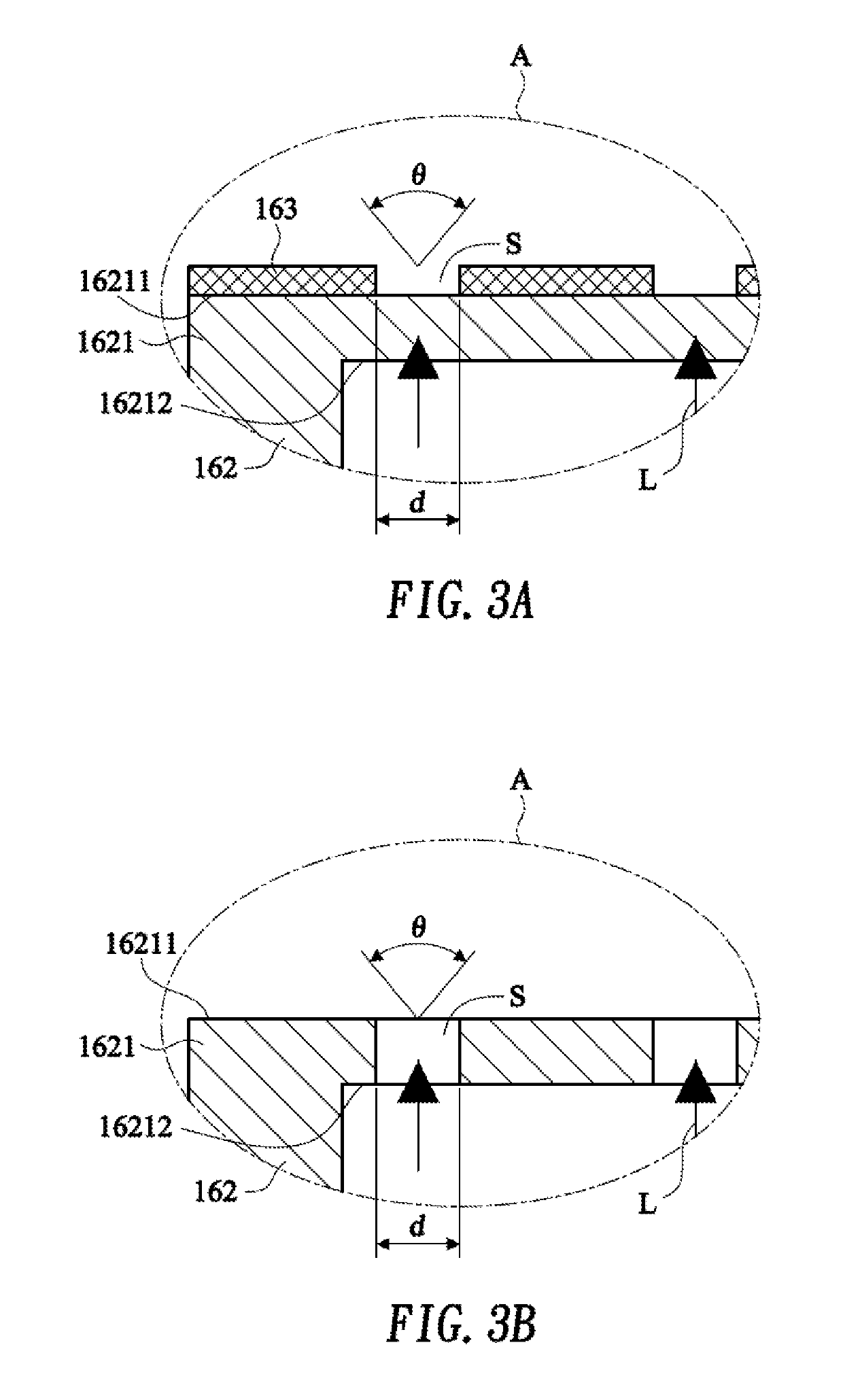
[0033]Still referring to FIG. 3A, FIG. 3A is an enlarged view of a slit structure in an area A in FIG. 2. In this embodiment, the shield 162 is a transparent cover body, and is made of PET. In addition, because the shield 162 is a transparent cover body to be passed through by the light ray L, a tone of light emitted from the light emitting module 16 can be adjusted by adjusting a color of the shield 162. Subsequently, light-proof ink is coated on the first surface 16211 of the light emergence part 1621 by means of a spray coating or printing process, to form an ink layer 163 including a plurality of slits S. The ink layer 163 including the plurality of slits S can be used as a diffraction grating. When the light ray L passes through the slits S of the ink layer 163, a diffraction effect occurs and the light ray L begins to expand to two sides. In this way, the irradiation angle of the light emitting module 16 can be adjusted by means of the slits S formed on the ink layer 163, and ...

second embodiment

[0034]Still referring to FIG. 3B, FIG. 3B is an enlarged view of a slit structure in an area A in FIG. 2. In this embodiment, the shield 162 is an opaque cover body, and is made of a reflector material. Subsequently, a plurality of slits S penetrating through the first surface 16211 and the second surface 16212 are formed in an area of the light emergence part 1621 by means of a punching process, and the light emergence part 1621 including the plurality of slits S can be used as a diffraction grating. When the light ray L passes through the slits S of the light emergence part 1621, a diffraction effect occurs and the light ray L begins to expand to two sides. In this way, the irradiation angle of the light emitting module 16 can be adjusted by means of the slits S penetrating through the first surface 16211 and the second surface 16212, and the evenness of light emergence of the light emitting module 16 is improved at the same time. Smaller widths d of the formed slits S indicate a ...


PUM


Abstract

The present invention provides a luminous keyboard, including: at least one key cap; a support plate; a support component, connected to the key cap and the support plate and capable of guiding the key cap to vertically move relative to the support plate; a thin film circuit board, disposed on the support plate; at least one light emitting component, configured to emit a light ray to the key cap; and a shield, covering the light emitting component, where there is a gap between the shield and the light emitting component, and the shield is provided with a diffraction grating at a position where the light ray passes through the shield.

Description

FIELD OF THE INVENTION[0001]The present invention relates to a keyboard, and particularly, to a luminous keyboard.BACKGROUND OF THE INVENTION[0002]In modern society, use of electronic products has become an indispensable part in life, and almost everything, such as food, clothing, living, transport, education, and entertainment, is related to the electronic products. Generally, a consumer electronic product is provided with a keyboard. To increase the practicability of the keyboard, a backlight module is usually disposed inside the keyboard, and the backlight module can project generated light rays to key caps of the keyboard, to enable a user to operate the keyboard in a dimly lit environment. On the other hand, the backlight module can also be used to implement a keyboard prompting function.[0003]In existing keyboard backlight technologies, a layer of a light guide plate structure may be disposed below a support plate of a keyboard, and corresponding light transmitting holes are d...

Claims


Application Information

Patent Timeline
Patent Type & Authority Patents(United States)
IPC IPC(8): G01D11/22H01H13/83H01H13/705H01H3/12
CPCH01H13/83H01H13/705H01H3/125H01H2219/058
Inventor YEH, TIEN-YUYANG, CHE-WEI
Owner PRIMAX ELECTRONICS LTD
Why Eureka
Try Eureka