System, apparatus and method for providing improved performance of aggregated/bonded network connections with multiprotocol label switching

a network connection and label switching technology, applied in the field of network communications, can solve the problems of network performance that is less than optimal, network performance across the entire network path, network performance that is generally slower than the network backbone, etc., and achieves the effect of increasing the long-haul

Active Publication Date: 2019-06-25
ADAPTIV NETWORKS INC
View PDF40 Cites 0 Cited by
  • Summary
  • Abstract
  • Description
  • Claims
  • Application Information

AI Technical Summary

Benefits of technology

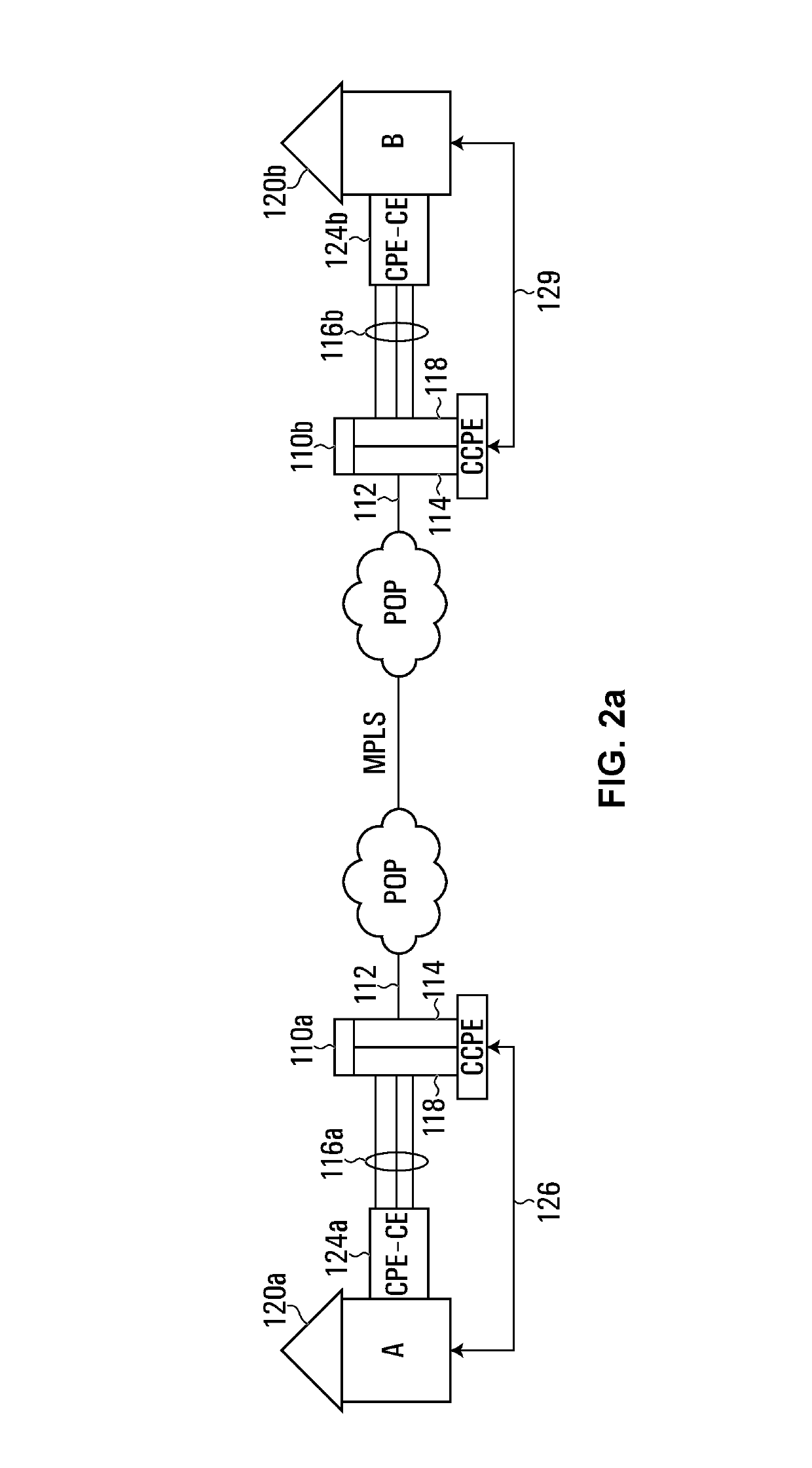
[0041]In one embodiment of the invention, a network system is provided for improving network communication performance between at least a first client site and a second client site, where the first client site and the second client site can be at a distance from one another that is such that would usually require long haul network communication, the network system comprising:

Problems solved by technology

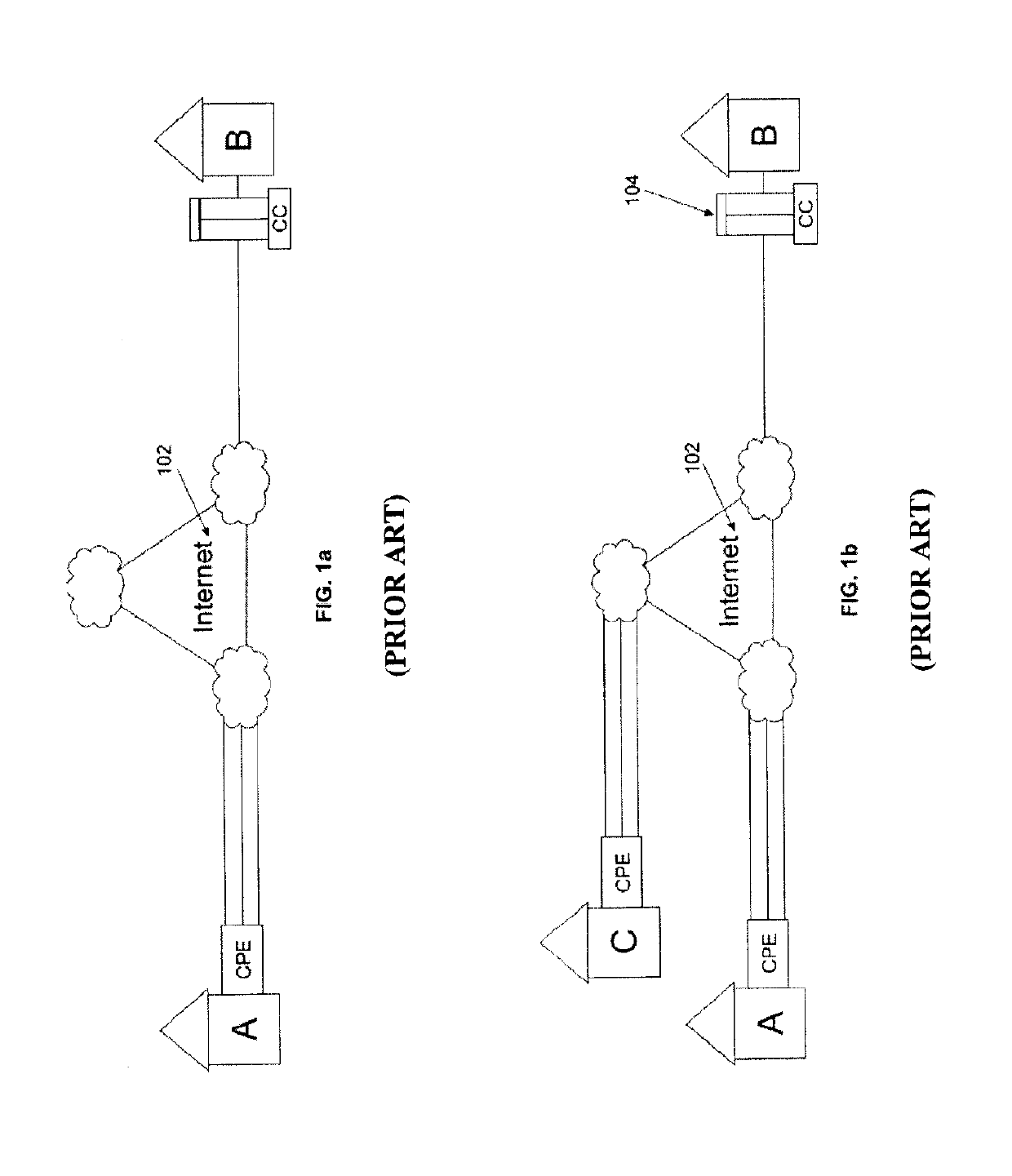
While the bonded / aggregated links provide significant network performance improvement over the connections available to carry network traffic for example from Location A to an access point to the backbone of a network (whether an Internet access point, or access point to another data network such as a private data network, an MPLS network, or high performance wireless network) (“network backbone”), the bonded / aggregated links are generally slower than the network backbone.
Prior art technologies including bonding / aggregation generally result in what is often referred to as “long haul” bonding / aggregation, which means that the bonded / aggregated links are maintained for example from Location A and Location B, including across the network backbone, which in many cases results in network impedance.
As a result, while bonding / aggregation provides improved network performance for example from Location A to the network backbone, network performance across the entire network path for example from Location A to Location B, may be less than optimal because the technology in this case does not take full advantage of the network performance of the network backbone.
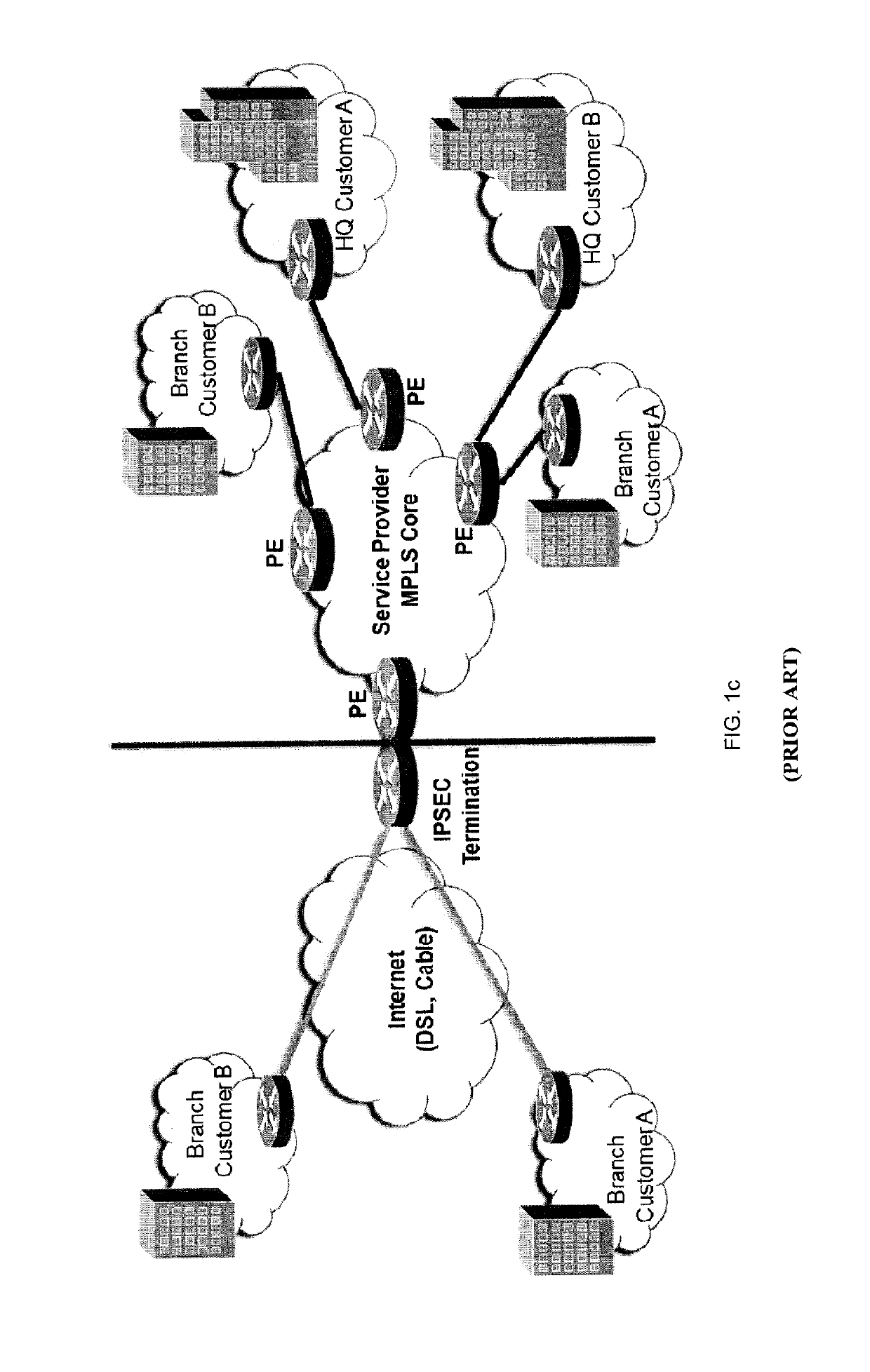
However, while typical IPSEC VPN can offer low price tag and reach, it lacks traffic prioritization / CoS capabilities and is hindered by poor provider Service Level Agreement (SLA) and / or Mean Time to Repair (MTTR).
IPSEC VPN for MPLS Edge has not been innovated; there is a need to evolve this type of MPLS access, disrupt the market and create end-customer demand.
Generally speaking, the MPLS market in North America is growing quickly, however, price of MPLS is suffering from commoditization of private networks and from customer demand for lower prices.
Despite such constraints, purchasing MPLS network can be as much as 30% more expensive compared to getting typical broadband network.
However, IPVPN has numerous drawbacks such as the lack of traffic prioritization and CoS capabilities.
IPVPN can also be hindered by poor provider service-level agreement (SLA) and mean time to repair (MTTR) on a given service or provider.
For customers who want to have an end-to-end VPN or MPLS network, at least one issue with MPLS networks is that they do not typically extend to the actual customer or client sites as the PE or ingress routers defining the “edge” of the MPLS network core are typically situated at network providers' premises.
However, in the current state of the art, most link aggregation technologies cannot connect to dissimilar or diverse carriers or connections.
In addition, an MPLS network is typically sold as a private product or service and thus cannot offer diverse carriers or network providers, but rather require physical local loop to the end customer using the same carrier or network provider.

Method used


Image

  • System, apparatus and method for providing improved performance of aggregated/bonded network connections with multiprotocol label switching
  • System, apparatus and method for providing improved performance of aggregated/bonded network connections with multiprotocol label switching
  • System, apparatus and method for providing improved performance of aggregated/bonded network connections with multiprotocol label switching

Examples


Embodiment Construction

[0093]The embodiments of the systems and methods described herein may be implemented in hardware or software, or a combination of both. These embodiments may be implemented in computer programs executing on programmable computers, each computer including at least one processor, a data storage system (including volatile memory or non-volatile memory or other data storage elements or a combination thereof), and at least one communication interface. For example, and without limitation, the various programmable computers may be a server, network appliance, set-top box, embedded device, computer expansion module, personal computer, laptop, personal data assistant, cellular telephone, smartphone device, UMPC tablets and wireless hypermedia device or any other computing device capable of being configured to carry out the methods described herein.

[0094]Program code is applied to input data to perform the functions described herein and to generate output information. The output information i...


PUM


Abstract

A network system, method, and device are provided for improving network communication performance between at least a first client site and a second client site, where the first client site and the second client site are at a distance from one another that is such that would usually require long haul network communication. The network system includes at least one network bonding / aggregation computer system for bonding or aggregating one or more diverse network connections so as to configure a bonded / aggregated connection that has increased throughput; and at least one network server component, configured to interoperate with the client site network component, the network server component including a server / concentrator or a cloud concentrator element that is implemented at an access point to an multiple protocol label switching network.

Description

CROSS REFERENCE TO RELATED APPLICATIONS[0001]This application is a continuation-in-part of U.S. patent application Ser. No. 13 / 958,009 filed on Aug. 2, 2013, which is a continuation-in-part of U.S. patent application Ser. No. 13 / 420,938, filed on Mar. 15, 2012, which is a continuation of U.S. patent application Ser. No. 12 / 269,439, filed on Nov. 12, 2008, all of which are hereby incorporated by reference.FIELD OF THE INVENTION[0002]Embodiments described herein relate generally to network communications and, in particular, to aggregating or bonding communications links so as to improve network performance or quality of services in regards to a variety of different networks including wired and wireless networks, and including Wide Area Networks (“WAN”).BACKGROUND OF THE INVENTION[0003]While the capacity of network connections has increased since the introduction of dial up, high speed connectivity is not ubiquitous in all regions. Also, bandwidth is not an unlimited resource and there...

Claims


Application Information

Patent Timeline
Patent Type & Authority Patents(United States)
IPC IPC(8): H04L12/709H04L12/64H04W76/16G06F9/455H04L29/06H04L12/28H04L5/00H04L12/70H04L45/243H04L45/42H04L45/50
CPCH04L45/245G06F9/45533H04L5/0098H04L12/2867H04L69/14H04W76/16H04L12/6418Y02D50/30H04L2012/5624Y02D30/50
Inventor SAAVEDRA, PATRICIO HUMBERTO
Owner ADAPTIV NETWORKS INC
Why Eureka
Try Eureka