Mixer for a vehicle exhaust system

a technology of vehicle exhaust and mixing machine, which is applied in the direction of machines/engines, transportation and packaging, human health protection, etc., can solve the problems of large droplet spraying system, inability to provide adequate urea transformation, and sensitive spray generated by small droplet dosers to recirculation flow, so as to reduce spray deposit formation

Active Publication Date: 2019-07-02
FAURECIA EMISSIONS CONTROL TECH GERMANY
View PDF37 Cites 15 Cited by
  • Summary
  • Abstract
  • Description
  • Claims
  • Application Information

AI Technical Summary

Benefits of technology

[0004]In one exemplary embodiment, a vehicle exhaust system includes an outer housing defining an internal cavity surrounding an axis, an inlet baffle configured to direct engine exhaust gas into the internal cavity, and an injector that is configured to spray a fluid into the internal cavity to mix with engine exhaust gas. An inner wall is spaced radially inward of an inner surface of the outer housing to define a gap. The inner wall has an impingement side facing the axis and a non-impingement side facing the gap. At least one heat transfer element is positioned within the gap and in is contact with at least one of the inner surface of the outer housing and the non-impingement side of the inner wall to transfer heat through the inner wall to the impingement side to reduce spray deposit formation.

Problems solved by technology

Systems that spray larger size droplets may not be able to provide adequate transformation of urea when used in more compact system configurations.
However, the spray generated by small droplet dosers is very sensitive to recirculation flow.
The deposits build up over time and can adversely affect system operation.

Method used


Image

  • Mixer for a vehicle exhaust system
  • Mixer for a vehicle exhaust system
  • Mixer for a vehicle exhaust system

Examples


Embodiment Construction

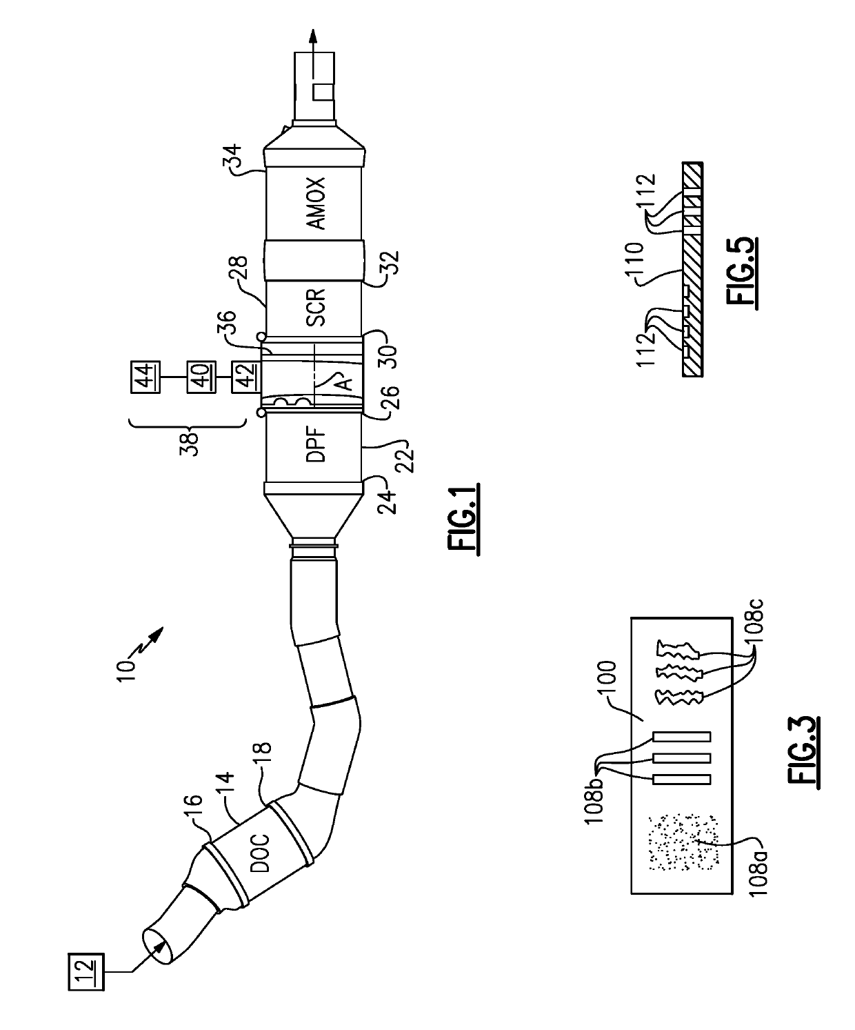
[0031]FIG. 1 shows a vehicle exhaust system 10 that conducts hot exhaust gases generated by an engine 12 through various exhaust components to reduce emission and control noise as known. The various exhaust components can include one or more of the following: pipes, filters, valves, catalysts, mufflers etc. After passing though the various exhaust components, the engine exhaust gas exits the system 10 to atmosphere as known.

[0032]In one example configuration shown in FIG. 1, the exhaust components direct engine exhaust gases into a diesel oxidation catalyst (DOC) 14 having an inlet 16 and an outlet 18. Downstream of the DOC 14 there may be a diesel particulate filter (DPF) 22 that is used to remove contaminants from the exhaust gas as known. The DPF has an inlet 24 and an outlet 26. Downstream of the DOC 14 and optional DPF 22 is a selective catalytic reduction (SCR) catalyst 28 having an inlet 30 and an outlet 32. The outlet 32 communicates exhaust gases to downstream exhaust compo...


PUM

PropertyMeasurementUnit
circumferential lengthaaaaaaaaaa
lengthaaaaaaaaaa
pressureaaaaaaaaaa

Abstract

A vehicle exhaust system includes an outer housing defining an internal cavity surrounding an axis, an inlet baffle configured to direct engine exhaust gas into the internal cavity, and an injector that is configured to spray a fluid into the internal cavity to mix with engine exhaust gas. An inner wall is spaced radially inward of an inner surface of the outer housing to define a gap. The inner wall has an impingement side facing the axis and a non-impingement side facing the gap. At least one heat transfer element is positioned within the gap and in is contact with at least one of the inner surface of the outer housing and the non-impingement side of the inner wall to transfer heat through the inner wall to the impingement side to reduce spray deposit formation.

Description

BACKGROUND OF THE INVENTION[0001]An exhaust system conducts hot exhaust gases generated by an engine through various exhaust components to reduce emissions and control noise. The exhaust system includes an injection system that injects a fluid such as a diesel exhaust fluid (DEF), or a reducing agent such as a solution of urea and water for example, upstream of a selective catalytic reduction (SCR) catalyst. A mixer is positioned upstream of the SCR catalyst and mixes engine exhaust gases and products of urea transformation. The injection system includes a doser that sprays the urea into the exhaust stream. The urea should be transformed as much as possible into ammonia (NH3) before reaching the SCR catalyst. Thus, the droplet spray size plays an important role in reaching this goal.[0002]The industry is moving towards providing more compact exhaust systems, which results in reduced volume of the system. Systems that spray larger size droplets may not be able to provide adequate tra...

Claims


Application Information

Patent Timeline
Patent Type & Authority Patents(United States)
IPC IPC(8): F01N3/28F01N3/035F01N3/20F01N13/10B01F3/04B01F5/06B01F5/02B01F5/04
CPCF01N3/2892F01N3/035F01N3/2066F01N3/28F01N13/10B01F3/04049Y02T10/24B01F5/0473B01F5/0614F01N2240/20F01N2610/1453Y02A50/2325B01F5/0268F01N13/08F01N13/14F01N3/021F01N2260/06F01N2610/02Y02A50/20Y02T10/12B01F23/2132B01F25/25B01F25/3141B01F25/4314
Inventor WILLATS, ROBINHORNBACK, JEROME BRIANPARRISH, TONYROHDE, JOHN G.KER, ERIC
Owner FAURECIA EMISSIONS CONTROL TECH GERMANY
Why Eureka
Try Eureka