Laser-induced spark ignition for an internal combustion engine

Inactive Publication Date: 2013-06-20
ROBERT BOSCH GMBH
View PDF2 Cites 11 Cited by
  • Summary
  • Abstract
  • Description
  • Claims
  • Application Information

AI Technical Summary

Benefits of technology

The present invention aims to make the operation of laser spark plugs in internal combustion engines more reliable. To achieve this, the invention reduces deposits on the combustion chamber window by providing a means for guiding, shaping, and / or generating laser radiation, and an aperture for the passage of the laser radiation into the combustion chamber. This results in improved reliability of the laser spark plug.

Problems solved by technology

In the case of the known device, it is to be regarded as a disadvantage that certain constituents of exhaust gases, for example oil ashes or soot, damage the combustion chamber window, for example by being deposited on the combustion chamber window and impairing its properties, in particular transmission for laser radiation.

Method used


Image

  • Laser-induced spark ignition for an internal combustion engine
  • Laser-induced spark ignition for an internal combustion engine
  • Laser-induced spark ignition for an internal combustion engine

Examples


Embodiment Construction

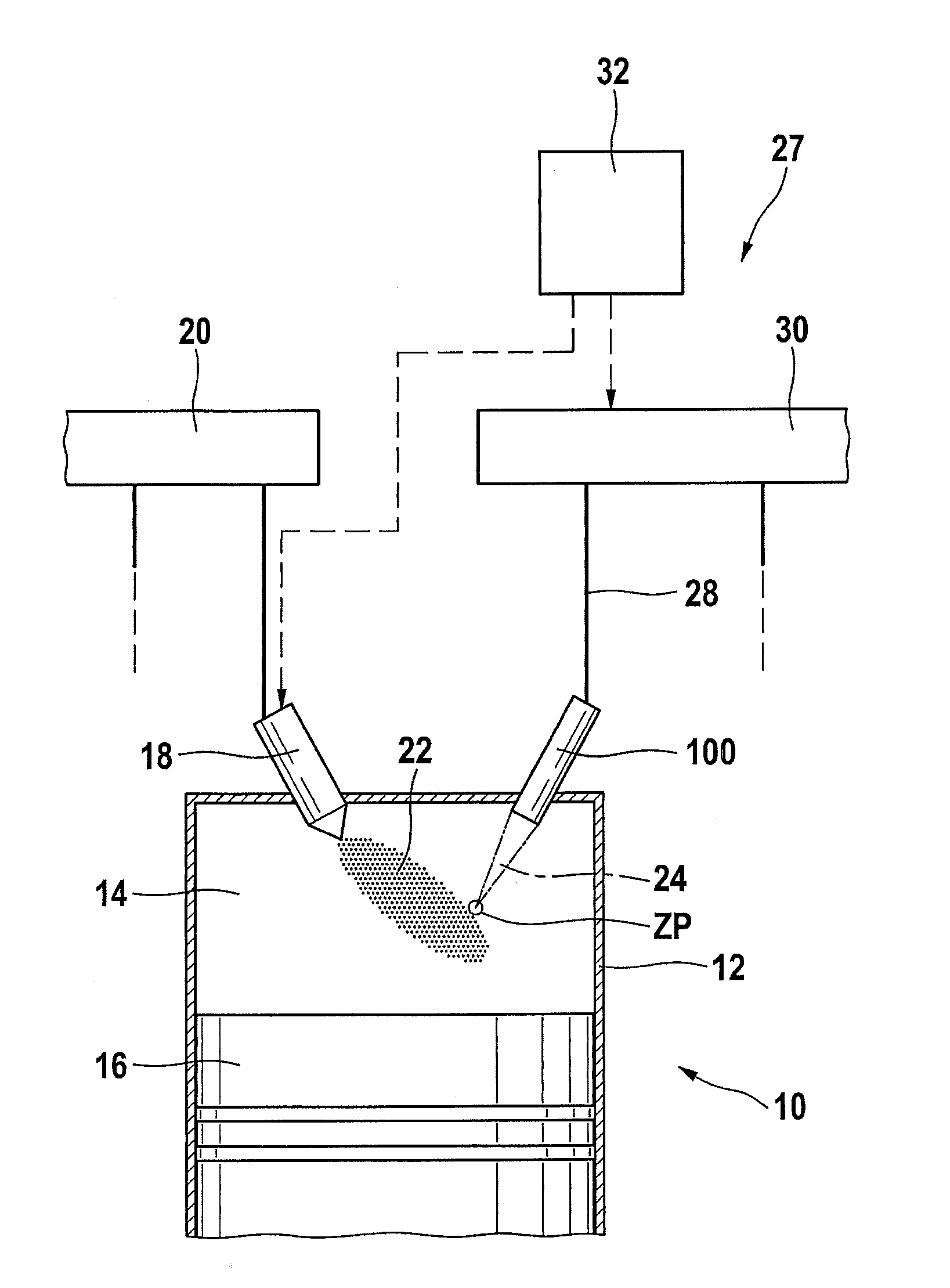
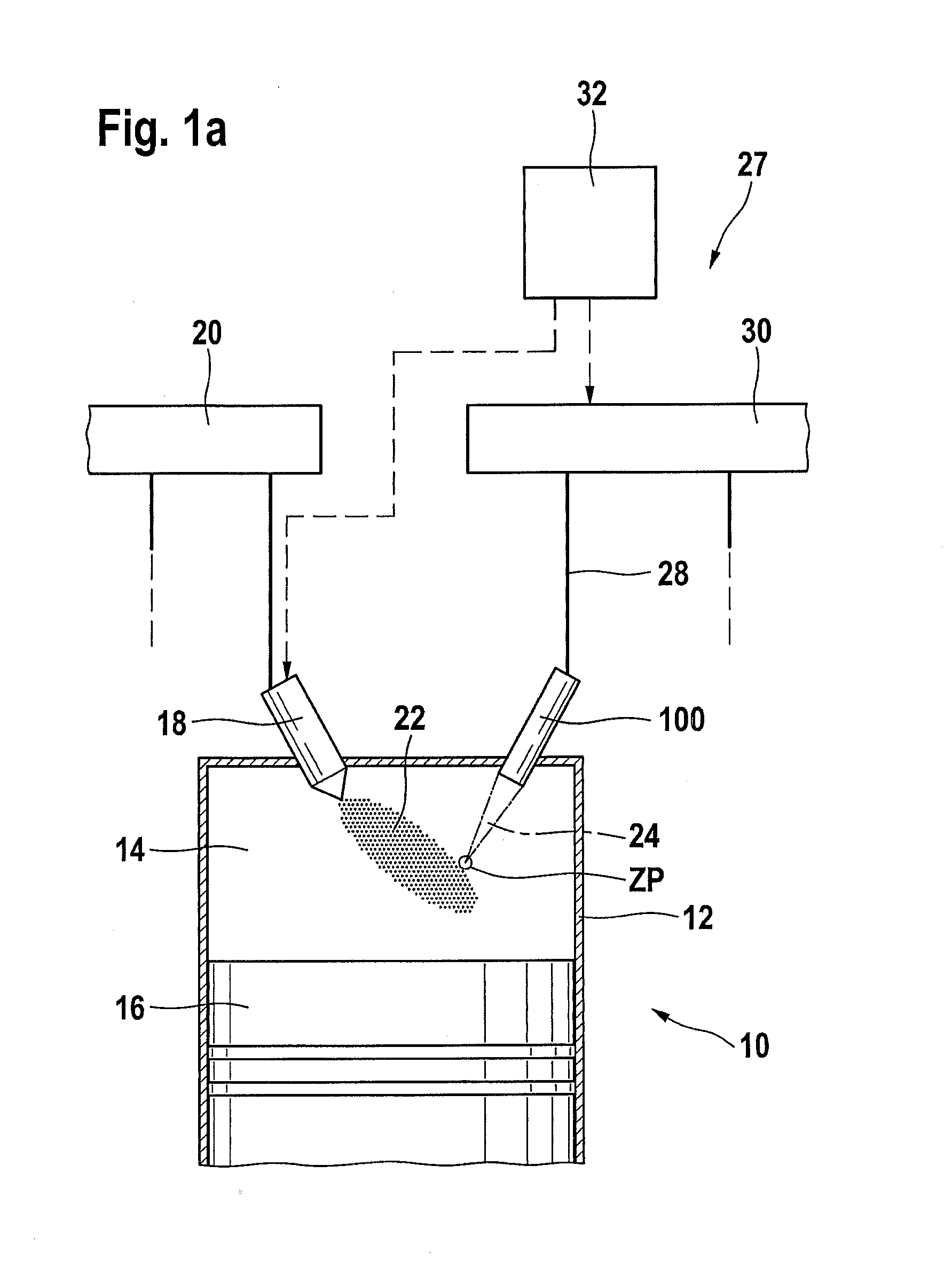
[0096]An internal combustion engine bears reference numeral 10 overall in FIG. 1a. It may be used to drive a motor vehicle, not shown. Internal combustion engine 10 includes a plurality of cylinders, only one of which is shown in FIG. 1, bearing reference numeral 12. A combustion chamber 14 of cylinder 12 is delimited by a piston 16. Fuel or previously mixed fuel / air mixture passes into combustion chamber 14 through an injector 18 which is connected to a fuel pressure reservoir 20 also referred to as a rail.

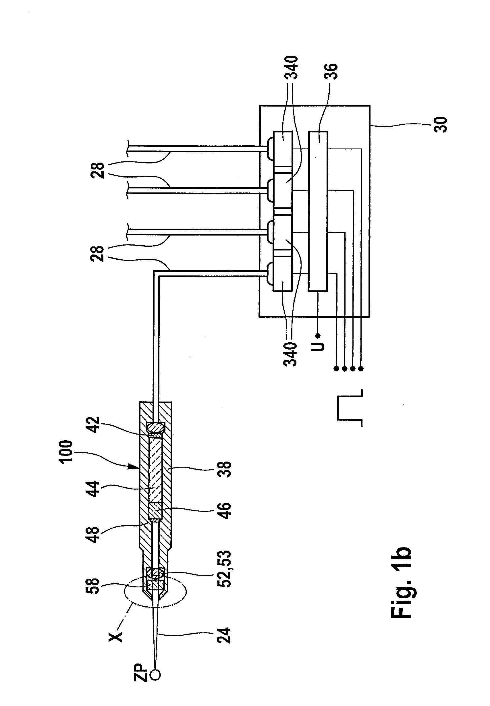
[0097]Fuel 22 injected into combustion chamber 14 or previously mixed fuel / air mixture is ignited by laser radiation 24 which is radiated into combustion chamber 14 from an ignition device 27 including a laser spark plug 100. For that purpose, laser spark plug 100 is supplied via a light-guiding device 28 with light that may, in particular, be pumping light provided by a light source 30. It is also possible to provide that light intended for the ignition is provided directly by l...


PUM


Abstract

Laser spark plug for an internal combustion engine has at least one laser unit for guiding, shaping and / or generating laser radiation, further including a combustion chamber window, and a housing which has, on the opposite side of the combustion chamber window from the laser unit, an aperture for the passage of the laser radiation guided, shaped and / or generated by the laser unit into a combustion chamber, the length of the aperture being 4 mm or more.

Description

BACKGROUND OF THE INVENTION[0001]1. Field of the Invention[0002]The present invention relates to a laser spark plug.[0003]2. Description of the Related Art[0004]There is known from published international patent application document WO 2005 / 066488 A1, for example, a device for ignition of an internal combustion engine, which device includes an ignition laser. The ignition laser has at the end thereof toward the combustion chamber a combustion chamber window which is transmissive for the laser pulses emitted by the ignition laser. At the same time, the combustion chamber window must withstand the high pressures and temperatures prevailing in the combustion chamber and must seal off the interior of the ignition laser from the combustion chamber. In that situation, high surface temperatures and pressures, and also soiling, for example in the form of oil ash deposits, particles, etc., may occur especially at the surface of the combustion chamber window facing the combustion chamber.[000...

Claims


Application Information

Patent Timeline
IPC IPC(8): F02P23/04
CPCF02P23/04F02P13/00
Inventor WOERNER, PASCALRAIMANN, JUERGENENGELHARDT, JOERGWEINROTTER, MARTIN
Owner ROBERT BOSCH GMBH
Why Eureka
Try Eureka