Laser-induced spark ignition for an internal combustion engine

a technology of laser ignition and internal combustion engine, which is applied in the direction of ignition sparking plugs, combustion engines, machines/engines, etc., can solve the problems of high surface temperature and pressure, damage to combustion chamber windows, and contamination, so as to reduce the formation of deposits on the combustion chamber windows, reduce the overall reliability of laser spark plugs, and reduce the effect of combustion chamber window deposits

Inactive Publication Date: 2013-06-06
ROBERT BOSCH GMBH
View PDF45 Cites 10 Cited by
  • Summary
  • Abstract
  • Description
  • Claims
  • Application Information

AI Technical Summary

Benefits of technology

The present invention improves the reliability of a laser spark plug for an internal combustion engine by reducing deposits on the combustion chamber window. This is achieved by providing a screen at the side of the housing opposite the means for guiding, shaping, and producing laser radiation. The screen influences the conditions to which the combustion chamber window is exposed, thus reducing the formation of deposits and improving the overall reliability of the laser spark plug.

Problems solved by technology

Here high surface temperatures and pressures, as well as contamination, for example in the form of deposits of oil ashes, particles, etc., may occur in particular at the surface of the combustion chamber window facing the combustion chamber.
In the known device, it is to be regarded as disadvantageous that particular components of exhaust gases, such as for example oil ashes or rust, damage the combustion chamber window, for example in that such components are deposited on the combustion chamber window and impair its properties, in particular its transmission for laser radiation.

Method used


Image

  • Laser-induced spark ignition for an internal combustion engine
  • Laser-induced spark ignition for an internal combustion engine
  • Laser-induced spark ignition for an internal combustion engine

Examples


Embodiment Construction

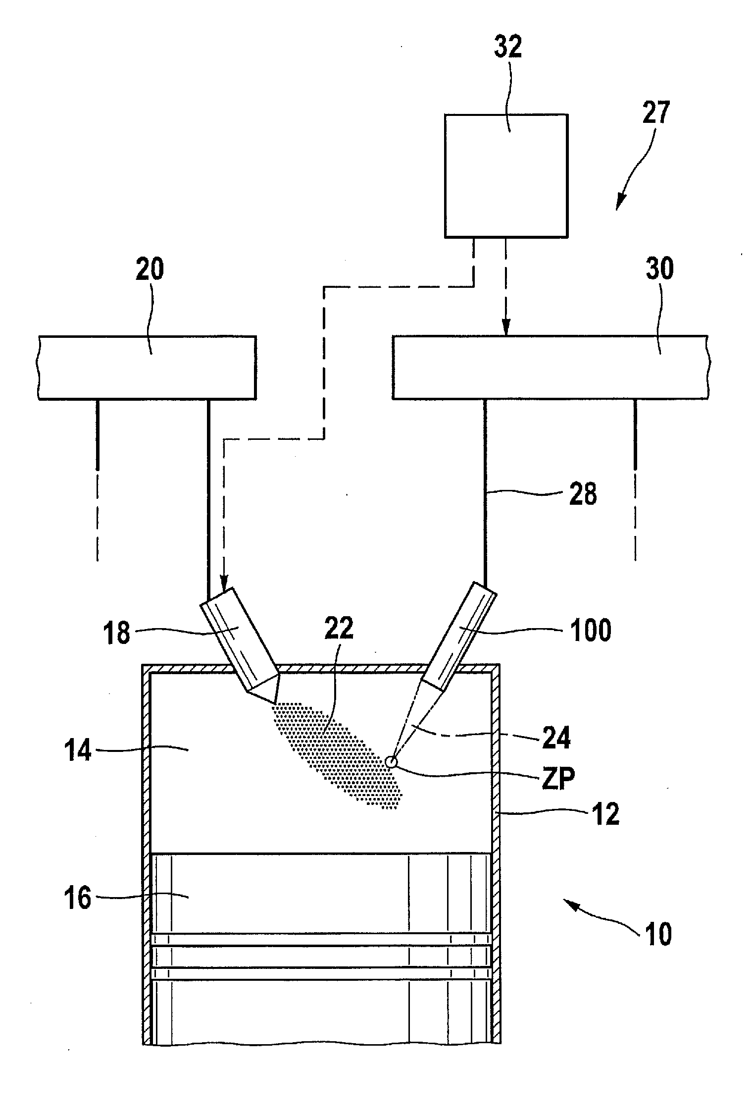
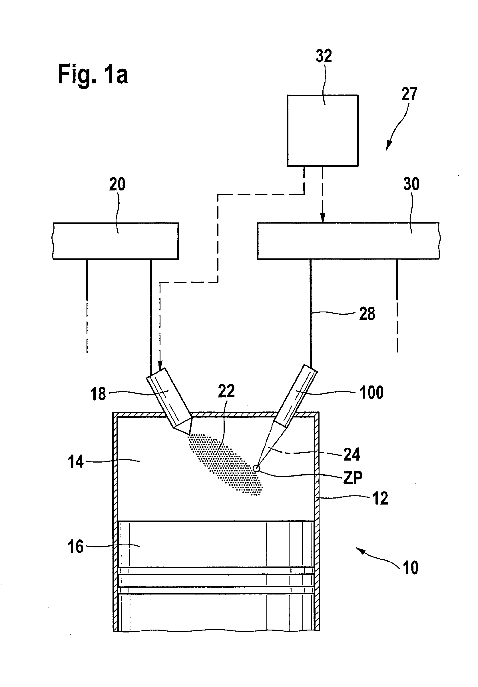
[0095]In FIG. 1a, an internal combustion engine is designated 10 overall. It can be used to drive a motor vehicle (not shown). Internal combustion engine 10 has a plurality of cylinders, of which FIG. 1 shows only one, designated by reference character 12. A combustion chamber 14 of cylinder 12 is limited by a piston 16. Fuel, or a previously mixed fuel-air mixture, moves into combustion chamber 14 through an injector 18, which is connected to a fuel pressure accumulator 20 also referred to as a rail.

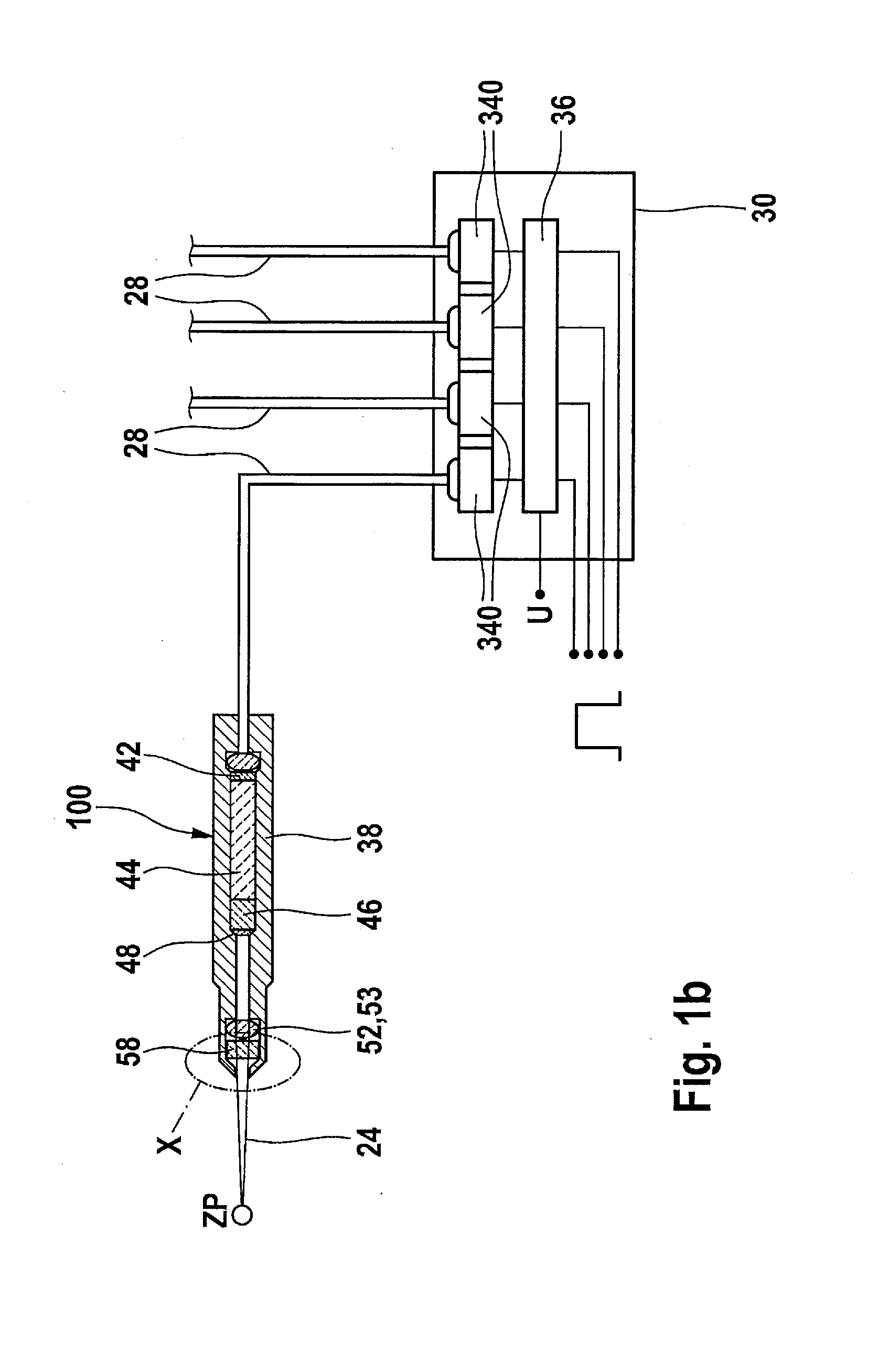
[0096]Fuel 22, or a previously mixed fuel-air mixture, injected into combustion chamber 14 is ignited by a laser radiation 24 that is radiated into combustion chamber 14 by an ignition device 27 that includes a laser spark plug 100. For this purpose, laser spark plug 100 is supplied with light via a light conductor device 28; this light can in particular be pumped light provided by a light source 30. Light source 30 can also immediately provide light provided for the ignition. Light sou...


PUM


Abstract

A laser spark plug for an internal combustion engine has at least one laser unit for guiding, shaping, and / or for producing laser radiation, a combustion chamber window, and a housing which has, at the side of the combustion chamber window situated opposite the laser unit, a screen for the passage of the laser radiation guided, shaped, and / or produced by the laser unit into a combustion chamber, the screen having a first end facing the combustion chamber and a second end facing away from the combustion chamber, the inner contour of the screen having an extremal cross-section in a region that is situated at a distance both from the first and second ends.

Description

BACKGROUND OF THE INVENTION[0001]1. Field of the Invention[0002]The present invention relates to a laser spark plug.[0003]2. Description of the Related Art[0004]For example from published international patent application document WO 2005 / 066488 A1, a device for igniting an internal combustion engine is known that includes an ignition laser. The ignition laser has, at its end at the combustion chamber side, a combustion chamber window that is transmissive for the laser impulses emitted by the ignition laser. At the same time, the combustion chamber window must withstand the high pressures and temperatures prevailing in the combustion chamber, and must seal the interior of the ignition laser against the combustion chamber. Here high surface temperatures and pressures, as well as contamination, for example in the form of deposits of oil ashes, particles, etc., may occur in particular at the surface of the combustion chamber window facing the combustion chamber.[0005]In the known device...

Claims


Application Information

Patent Timeline
Patent Type & Authority Applications(United States)
IPC IPC(8): F02P23/04
CPCF02P23/04F02P13/00
Inventor WOERNER, PASCALRAIMANN, JUERGENENGELHARDT, JOERGWEINROTTER, MARTIN
Owner ROBERT BOSCH GMBH
Why Eureka
Try Eureka