Power conversion apparatus with low power consumption and low cost

US10340802B1Active Publication Date: 2019-07-02POWER FOREST TECH

Image

  • Power conversion apparatus with low power consumption and low cost
  • Power conversion apparatus with low power consumption and low cost
  • Power conversion apparatus with low power consumption and low cost

Examples


Embodiment Construction

[0023]In order to make the invention more comprehensible, embodiments are described below as the examples to show the invention. Moreover, elements / components / steps with same reference numerals represent same or similar parts in the drawings and embodiments. In addition, the term ā€œcoupleā€ used in the specification may be ā€œindirect coupleā€ or ā€œdirect coupleā€.

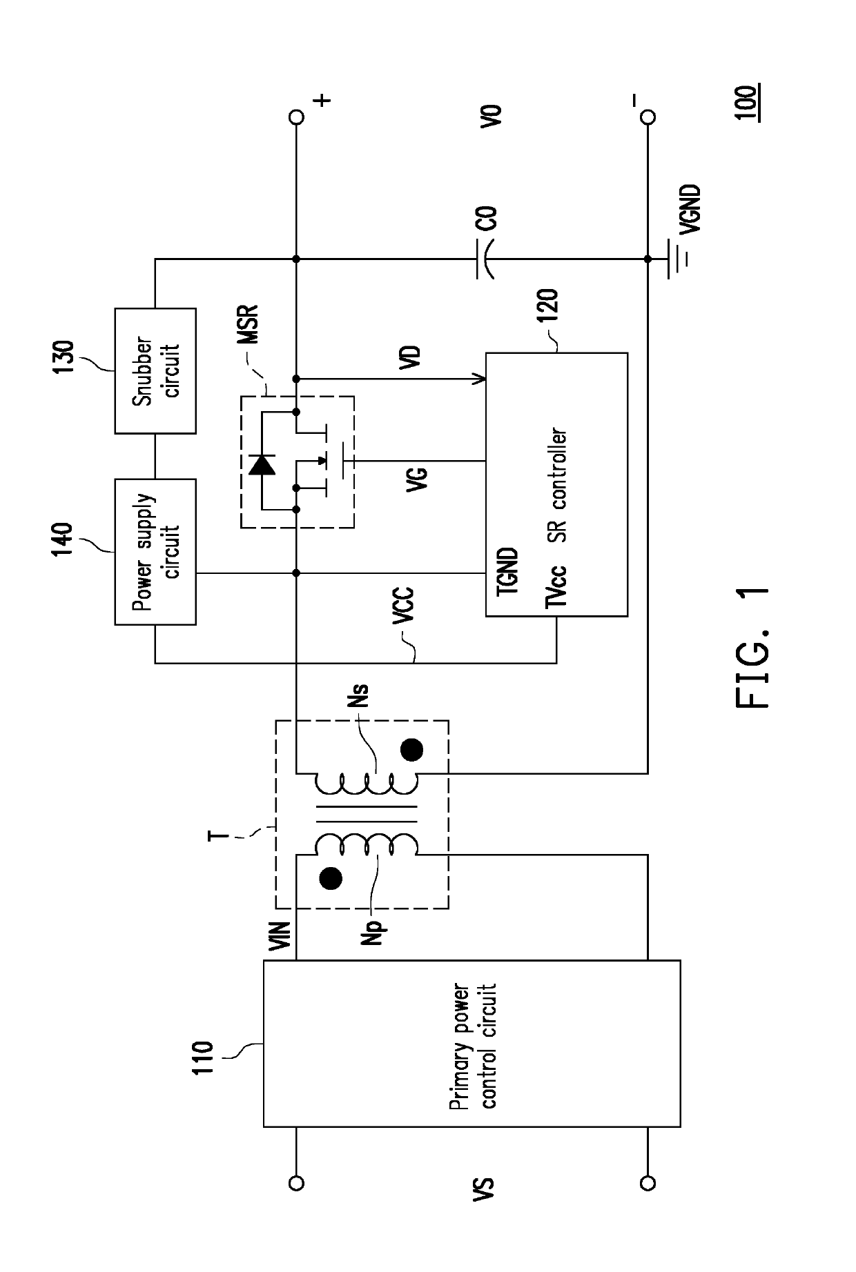
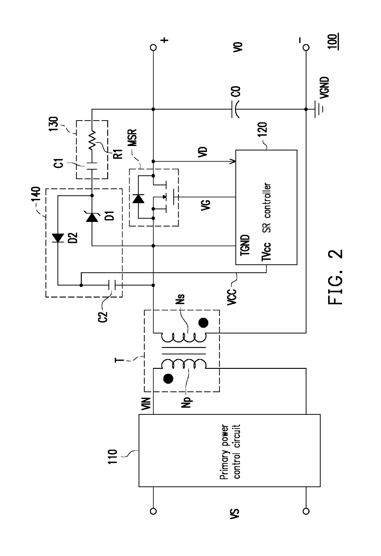
[0024]An architecture of a power conversion apparatus of the invention may be a flyback type, a push-pull type, a forward type, a half-bridge type, a full-bridge type or any other type, but the architecture of the power conversion apparatus is not particularly limited in the invention. However, for descriptive convenience, the power conversion apparatus having a flyback architecture is taken as an example for explanation, while the power conversion apparatus having any other architecture may derive from this.

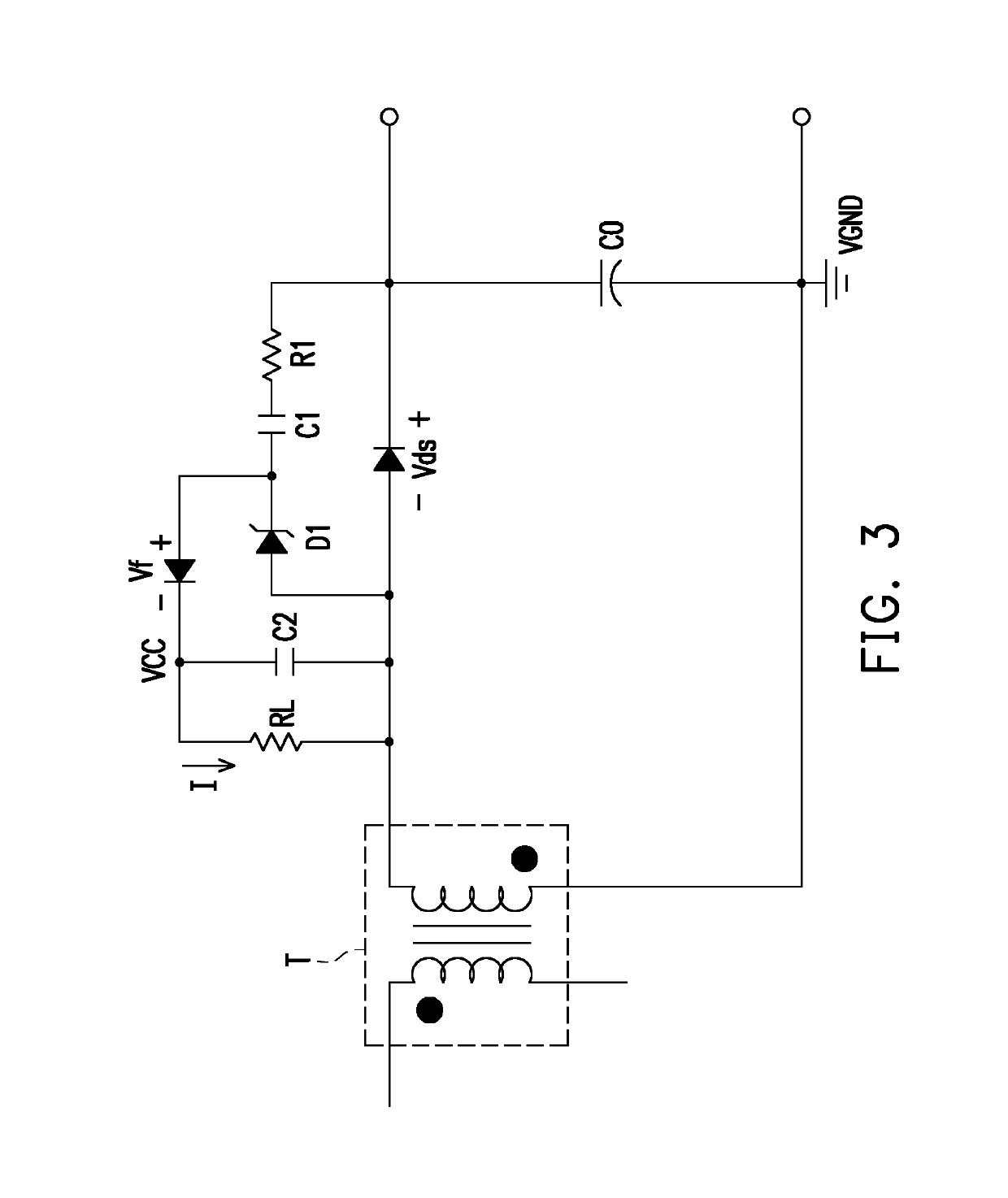
[0025]FIG. 1 is a schematic circuit block diagram illustrating a power conversion apparatus according to an embodiment of t...


PUM


Abstract

A power conversion apparatus including a synchronous rectification (SR) transistor, a SR controller and a snubber circuit is provided. The SR controller is coupled to the SR transistor to control the SR transistor. A ground terminal of the SR controller is coupled to a source terminal of the SR transistor, and a power terminal of the SR controller is coupled to a system voltage. A first terminal of the snubber circuit is coupled to a drain terminal of the SR transistor. A second terminal of the snubber circuit is coupled to the power terminal of the SR controller. The snubber circuit obtains power from the drain terminal of the SR transistor and provides the system voltage accordingly.

Description

CROSS-REFERENCE TO RELATED APPLICATION[0001]This application claims the priority benefit of Taiwan application serial no. 107122497, filed on Jun. 29, 2018. The entirety of the above-mentioned patent application is hereby incorporated by reference herein and made a part of this specification.BACKGROUNDField of the Invention[0002]The invention relates to a power conversion apparatus and more particularly, to a power conversion apparatus with low power consumption and low cost.Description of Related Art[0003]A power conversion apparatus is an indispensable element in modern electronic apparatus. In a pulse width modulation (PWM)-based power conversion apparatus, a secondary side of the power conversion apparatus is usually provided with a rectification diode. Since the rectification diode in a turned-on state has large power consumption, a synchronous rectification (SR) transistor with a low on-resistance may be used to replace the rectification diode. Under such architecture, an SR c...

Claims


Application Information

Patent Timeline
02 Jul 2019
Publication
US10340802B1
IPC
H02M3/158; H02M1/34; H02M1/00; H02M7/219
CPC
H02M3/1584; H02M1/34; H02M2001/0032; H02M2001/0006; H02M7/219; H02M7/217; H02M1/0006; H02M1/0038
Inventors
KE, PO-JEN