
Self priming and evacuating liquid sterilizing system

a liquid sterilizing system and self-priming technology, applied in the direction of vacuum distillation separation, evaporator regulation/control, treatment control/steering, etc., can solve the problems of insufficient sterilization, ineffective use of light, and inconvenient use of light, so as to achieve safe and effective decontamination of aqueous liquids, low cost, accurate, predictively and variably controlled

Active Publication Date: 2019-07-09
TOTH ANANISE +1
View PDF21 Cites 3 Cited by
  • Summary
  • Abstract
  • Description
  • Claims
  • Application Information

AI Technical Summary

Benefits of technology

The patent describes a system that uses sterilized water to cool down a chamber. When the chamber reaches a certain temperature, a valve is opened and the water flows out of the chamber. This creates a void that causes the water to evaporate and cool down the chamber. The technical effect is that the system helps to control the temperature of the chamber and ensures that the water remains sterilized.

Problems solved by technology

With these statistics, it is astounding that no water purification method is currently available and sufficiently low in cost to prevent such water borne illnesses.
However, use of light is known to sometimes be ineffective and at other times be unpredictable when used in water that has variable light transmission quality.
While pasteurization has long been used to improve safety and lengthen term for storage of milk, pasteurized milk has also been recognized as still containing microbes and, therefore, is not completely sterilized.
Also, Ashton does not teach regulating pressure at a temperature required for sterilization.

Method used


Image

  • Self priming and evacuating liquid sterilizing system
  • Self priming and evacuating liquid sterilizing system
  • Self priming and evacuating liquid sterilizing system

Examples


Embodiment Construction

[0049]In this description, the term proximal is used to indicate nearness of a referenced item to the object of the sentence describing its position. The term distal should be interpreted as indicating “away from” a referenced item. Numbers and primes of the same numbers are used to indicate items of related mechanics and function, but which may have physical differences. It should be noted that embodiments disclosed herein and hereafter are exemplary.

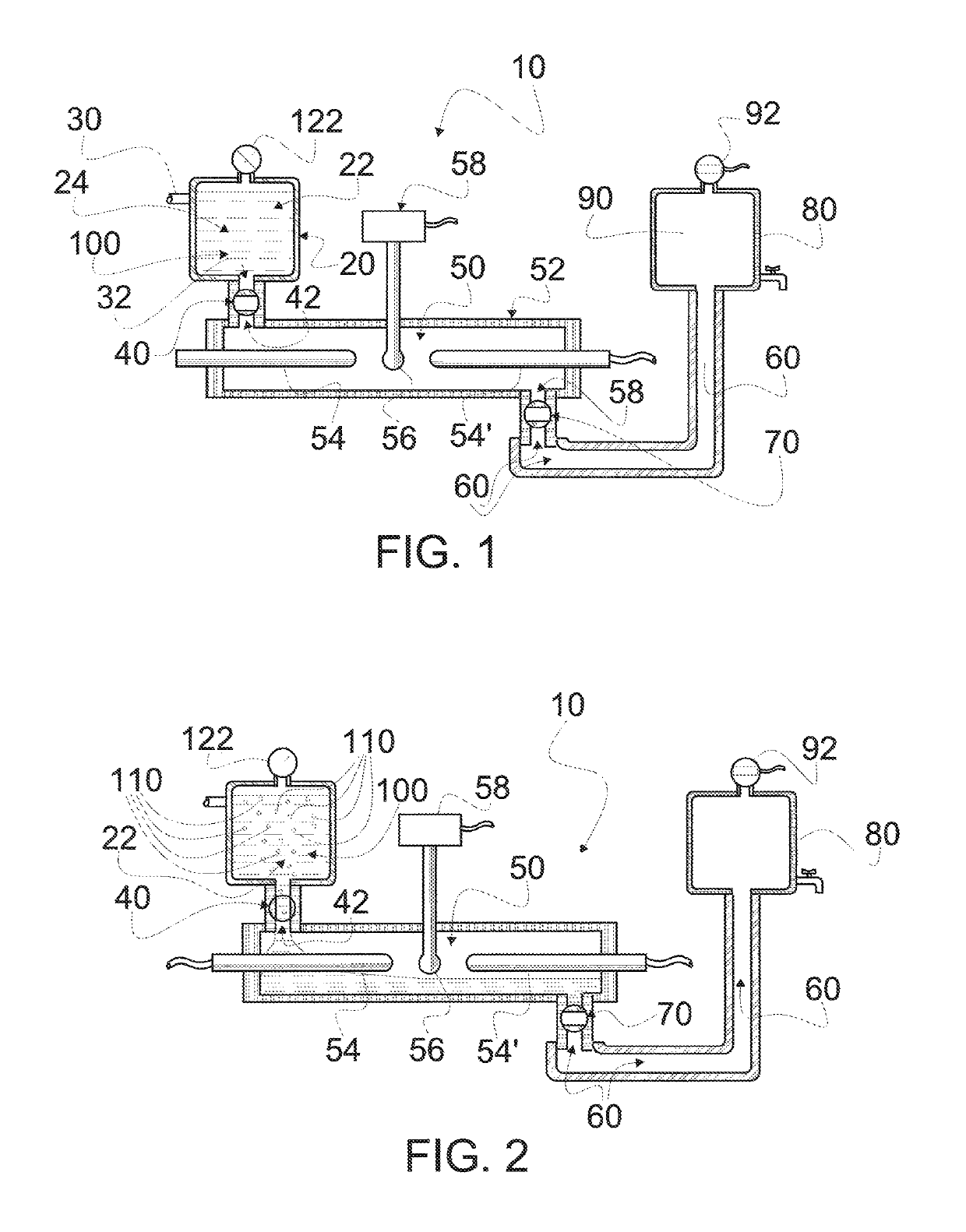
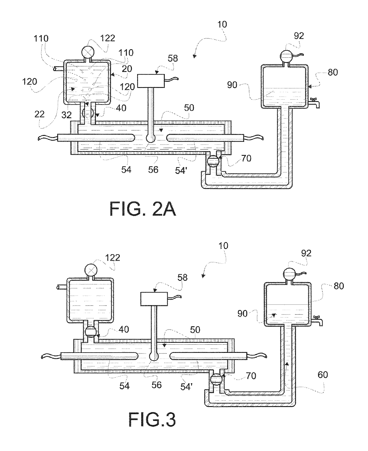
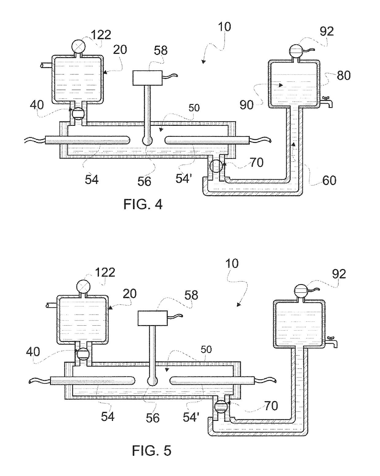
[0050]Reference is now made to the embodiment illustrated in FIG. 1 wherein a cyclic sterilizing system 10 made according to the present invention is seen to comprise a source housing 20 which comprises a vessel 22 which receives a supply, of pressurized liquid 24 to be sterilized, through a source pipe 30. Housing 20 comprises an exit orifice 32, fluid flow through which is gated by a first or inlet valve 40. When valve 40 is opened, a pathway 42 permits liquid displacement from housing 20 into a heating chamber 50 (and retrograde gas...


PUM

PropertyMeasurementUnit
pressure dropaaaaaaaaaa
pressureaaaaaaaaaa
critical temperatureaaaaaaaaaa

Abstract

Apparatus and method for providing a self priming, self evacuating, cyclicly operating system in which liquid is disposed in a closed, fluid tight heating chamber for sterilization. Only a single parameter, temperature, is monitored to accomplish a desired liquid SAL. A pair of valves are singly and sequentially opened and closed within four phases (steps) to provide for liquid displacement. Operation cycles through four phases which include opening an inlet valve for filling the heating chamber, heating liquid to a predetermined temperature at which the liquid is sterilized to the desired SAL, opening an outlet valve whereby internally generated pressure delivers sterilized liquid to a dispensing container and a delay for keeping valve opening separate.

Description

FIELD OF INVENTION[0001]This invention relates to apparatus and methods by which aqueous (water based) liquids are decontaminated, collected and used for culinary purposes. This invention is further related to methods which decontaminate such aqueous liquids without use of chemical or light energy processes to a predetermined sterility assurance level (SAL).BACKGROUND OF THE INVENTION[0002]There is an ever increasing need for new, more effective, efficient and lower cost methods for decontaminating water and other water based (aqueous) liquids. As an example, Center for Disease Control and Prevention (CDC) reports in a Mar. 6, 2003, report on BACTERIAL WATERBORNE DISEASES that each year there are 3.5 billion episodes of illness and a resulting three million estimated deaths caused by contaminated water and despite global efforts improvements have barely kept pace with population increases. From an Emerging Infectious Diseases article, dated 10 Oct. 2005, it was reported that sevente...

Claims


Application Information

Patent Timeline
Patent Type & Authority Patents(United States)
IPC IPC(8): B01D3/42C02F1/00C02F1/02
CPCC02F1/02C02F1/008B01D3/42C02F1/006C02F2201/005C02F2303/04C02F2209/03C02F2301/066C02F2301/04C02F2209/02C02F2209/005B01D1/0082B01D3/10C02F1/06A23L3/003C02F1/048
Inventor BOWEN, JOHN GUY
Owner TOTH ANANISE
Learn More