Production method for a bonded optical member and a virtual image display device

a production method and optical member technology, applied in the direction of optics, instruments, optical light guides, etc., can solve the problems of unfavorable see-through properties disturbed, and achieve the effect of simple and reliable formation of the surface of the bonding region

Active Publication Date: 2019-07-09
SEIKO EPSON CORP
View PDF20 Cites 0 Cited by
  • Summary
  • Abstract
  • Description
  • Claims
  • Application Information

AI Technical Summary

Benefits of technology

[0007]In the production method for a bonded optical member, smoothing is achieved by forming the smoothing film-formed face on the bonding surface which is the surface of the bonding region between the first base material and the second base material also on at least the surfaces of adjacent regions in the bonding of the surfaces of the first base material and the second base material, and at this time, the smoothing assisting treatment on the bonding surface or a region corresponding to the bonding surface is performed. According to this configuration, sufficient smoothing can be achieved by the synergistic effect of smoothing by the smoothing film-formed face and the smoothing assisting treatment, and the bonded optical member in which the surface of the bonding region is simply and reliably formed in a favorable state can be produced.
[0017]A production method for a virtual image display device according to an aspect of the invention produces a virtual image display device which includes a bonded optical member produced by the production method for a bonded optical member according to any of the aspects of the invention as a light guiding device. In this case, by including the bonded optical member as a light guiding device, the bonding region can be brought into a favorable state, and therefore, for example, a virtual image display device in a favorable see-through state can be produced.
[0019]In the above light guiding device, a bonding surface of a bonding section formed between a first base material and a second base material is flattened by polishing, and the polished face which is the flattened face is smoothed by the smoothing film-formed face, whereby a region from the surface of the first base material to the surface of the second base material including the bonding surface therebetween is smoothed and therefore can be simply and reliably brought into a favorable state.

Problems solved by technology

However, for example, in a case where the surface coat layer is formed before bonding, and thereafter, the adhesive is applied, even if the formation of a concavely recessed region can be avoided, it is not necessarily the case that a favorable state where the surface between the two optical members and the bonding region where the adhesive is applied is sufficiently smoothed can be ensured, and a favorable see-through property may be disturbed.

Method used


Image

  • Production method for a bonded optical member and a virtual image display device
  • Production method for a bonded optical member and a virtual image display device
  • Production method for a bonded optical member and a virtual image display device

Examples


first embodiment

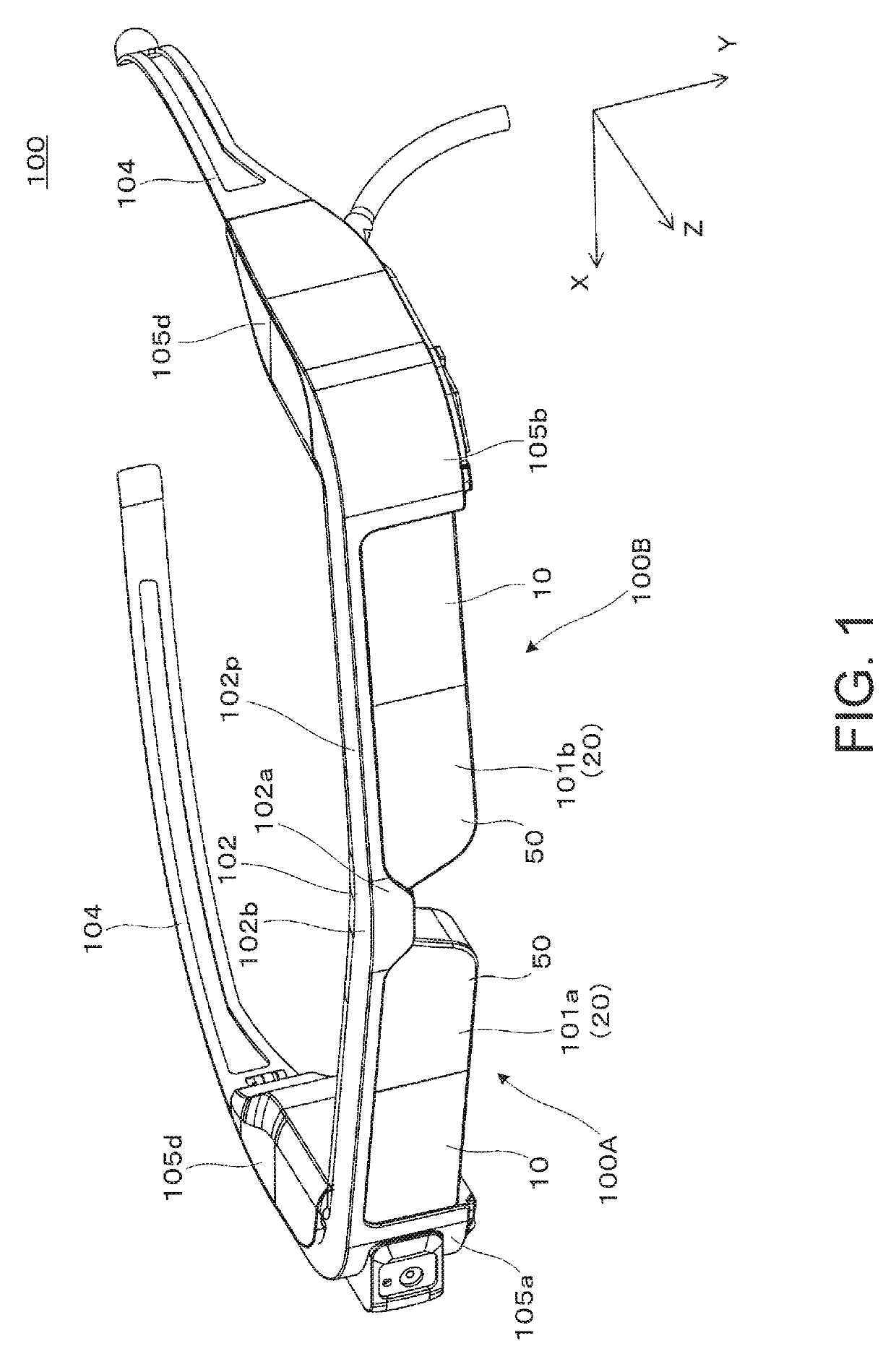
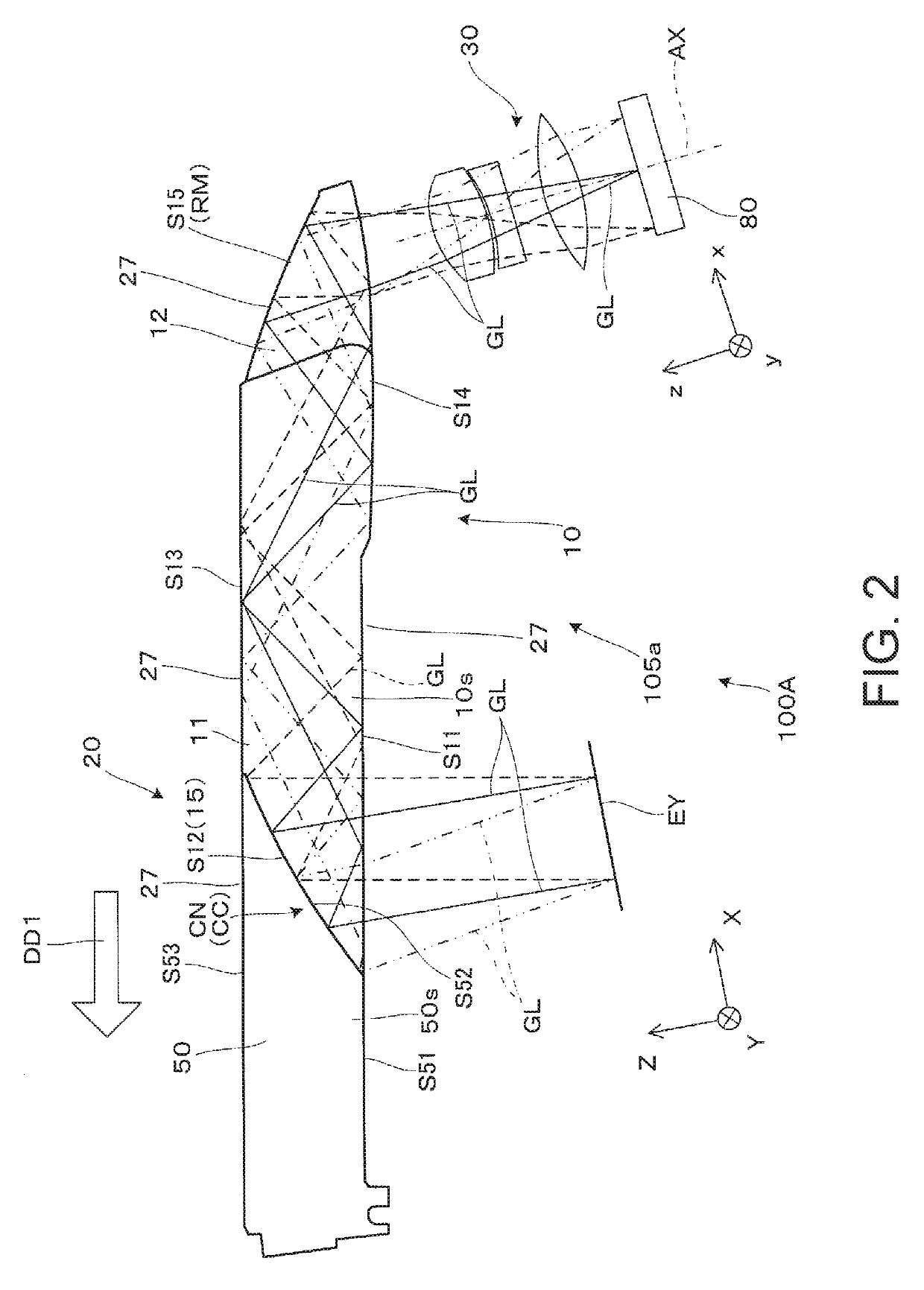
[0035]Hereinafter, with reference to FIG. 1 or the like, a virtual image display device including a light guiding device as a bonded optical member according to a first embodiment of the invention will be described in detail including a production method for the bonded optical member.

[0036]As shown in FIGS. 1 and 2, a virtual image display device 100 according to this embodiment is a head-mounted display (HMD) with an external appearance like eyeglasses, and is capable of allowing an observer or a user who wears this virtual image display device 100 to visually recognize an image light (a video light) based on a virtual image, and also is capable of allowing the observer to visually recognize or observe an external image in a see-through manner. The virtual image display device 100 includes a first display device 100A, a second display device 100B, and a frame section 102. In particular, in this embodiment, in the respective display devices 100A and 100B, light guiding members 10 an...

second embodiment

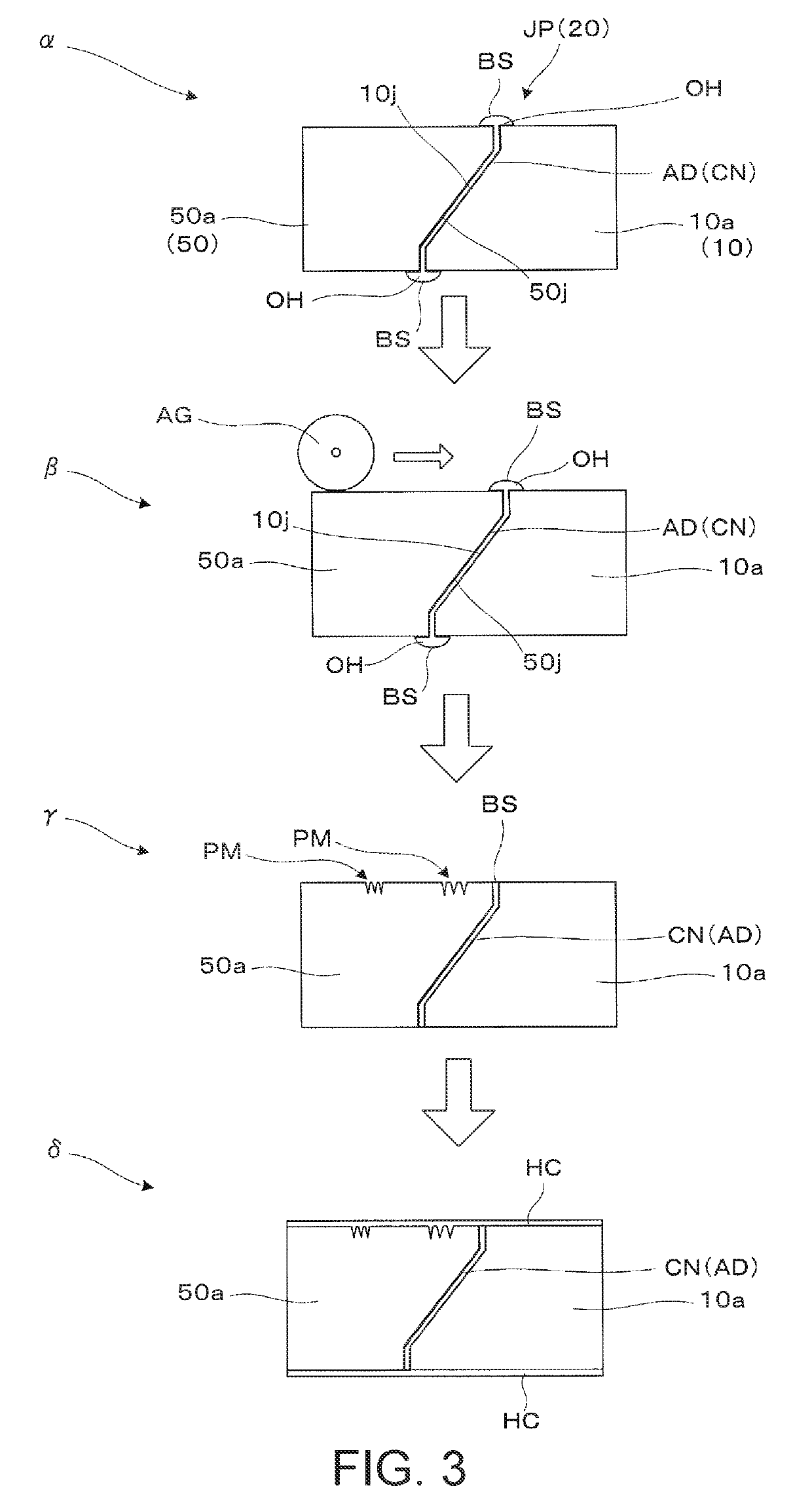
[0067]Hereinafter, with reference to FIG. 6, a production method for a bonded optical member which can be applied as a light guiding device to be used in a head-mounted display device according to a second embodiment will be described. FIG. 6 is a view for illustrating an example of a production process for a bonded optical member according to this embodiment.

[0068]This embodiment is different from the first embodiment in that the bonded optical member JP in which the surface is smoothed is produced by performing a treatment of forming the assisting film-formed face by further performing film formation on the hard coat layer HC after forming the smoothing film-formed face of the hard coat layer HC instead of polishing using an abrasive grain or the like as the smoothing assisting treatment. In other words, in this embodiment, a multilayer film having a structure of two or more layers including the hard coat layer HC is formed on the base material, whereby smoothing is achieved by th...


PUM

PropertyMeasurementUnit
refractive indexaaaaaaaaaa
optical performanceaaaaaaaaaa
thicknessaaaaaaaaaa

Abstract

By forming a hard coat layer on a bonding surface which is a surface of a bonding region between a first base material and a second base material, smoothing is achieved, and as a smoothing assisting treatment before forming the hard coat layer, the surfaces of the base materials are flattened by polishing on the bonding surface or a region corresponding to the bonding surface. By the synergistic effect of smoothing by formation of the hard coat layer and a flattening treatment by polishing as the smoothing assisting treatment, sufficient smoothing is achieved.

Description

BACKGROUND1. Technical Field[0001]The present invention relates to a production method for a bonded optical member which can be utilized as a light guiding device that presents a video formed by, for example, a video element or the like to an observer, a production method for a virtual image display device, a light guiding device, and a virtual image display device.2. Related Art[0002]There has been known a bonded optical member in which two optical members are bonded with an adhesive as a bonded optical member which can be applied to, for example, a virtual image display device such as a head-mounted display (hereinafter also referred to as “HMD”) to be worn on the head of an observer (see, for example, Japanese Patent No. 5256488 (Patent Document 1)).[0003]In Patent Document 1, as a method for removing an adhesive protruding from a bonding face when bonding two optical members by wiping off, a surface coat layer is formed on each of the optical members before bonding with the adhe...

Claims


Application Information

Patent Timeline
Patent Type & Authority Patents(United States)
IPC IPC(8): G02B27/01F21V8/00G02B1/14G02B27/00
CPCG02B27/0172G02B1/14G02B6/0048G02B27/0006G02B2027/0178G02B6/0038G02B2027/0125G02B2027/0174G02B6/002
Inventor MIYAO, TOSHIAKITAKAGI, MASAYUKITAKEDA, TAKASHIKOMATSU, AKIRA
Owner SEIKO EPSON CORP
Why Eureka
Try Eureka