Method for Manufacturing Optical Fiber Base Material and Optical Fiber Base Material

a manufacturing method and technology of optical fiber, applied in the field of base materials, can solve the problems of troublesome and costly processing steps, and achieve the effects of long optical fiber, low scattering loss, and high dimensional precision

Inactive Publication Date: 2020-06-25
KOHOKU KOGYO CO LTD
View PDF3 Cites 0 Cited by
  • Summary
  • Abstract
  • Description
  • Claims
  • Application Information

AI Technical Summary

Benefits of technology

[0080]According to a manufacturing method of the present invention, a rod containing SiO2 family glass for core is arranged in the center of a container, and in this state, a hardening-resin-containing SiO2 glass raw material solution for cladding layer and a hardener are poured into the container, the glass raw material solution is solidified through a self-hardening reaction, the container is then removed from the solidified material, and the solidified material is dried and heated in chlorine gas, whereby an optical fiber base material in which a SiO2 cladding layer is formed in the outer periphery of the rod containing SiO2 family glass for core can be obtained. According to the manufacturing method of the present invention, if the size of the container (in the case of a circular container, the inner diameter and the length (height) of the container) is set to be large, a large-diameter optical fiber base material can be easily achieved, whereby a long optical fiber can be obtained.
[0081]In addition, the glass raw material liquid in the form of liquid comes into contact with the outer periphery of the rod containing SiO2 family glass for core, and is solidified, whereby the SiO2 cladding layer is formed. Hence, the outer peripheral surface of the rod and the SiO2 cladding layer are in tight contact with each other, and the SiO2 cladding layer of uniform composition can be thickly formed in the outer periphery of the rod. As a result, the interface between the outer periphery of the rod containing SiO2 family glass for core and the SiO2 cladding layer can be made adequately smooth, and hence an optical fiber with an very low scattering loss on this interface can be achieved.
[0082]Further, according to the present invention, with the use of a stainless-steel container having an inner surface that is mirror-polished to a surface roughness of 0.2 μm or less (preferably 0.01 μm to 0.03 μm), the surface roughness of the outer peripheral surface of the SiO2 cladding layer can be made adequately smooth, that is, equal to or less than 0.4 μm. Moreover, because the outer shape of the SiO2 cladding layer can be achieved with high dimensional precision by the inner shape of the container, an optical fiber base material kept with high dimensional precision can be achieved, and an optical fiber base material having high straightness and roundness can be manufactured. Accordingly, an optical fiber obtained by drawing such an optical fiber base material can have extremely high mechanical strength and dimensional precision. It is experimentally known that, if the hardening-resin-containing SiO2 glass raw material solution for cladding layer and the hardener are poured into the container and are solidified and if the solidified material is then heated at high temperature, the solidified material is shrunk to about 82% of the size before the heating at high temperature, and hence the outer diameter of the optical fiber base material may be designed in consideration of this shrinkage ratio (18% (100-82)%. Moreover, even if the solidified material is shrunk, the outer peripheral surface of the obtained optical fiber base material (SiO2 cladding layer) is kept in a mirrored state.
[0083]Moreover, the glass raw material solution in the form of liquid comes into contact with the outer periphery of the rod containing SiO2 family glass for core, and is solidified, whereby the SiO2 cladding layer of uniform composition is formed. Hence, an optical fiber with a very low scattering loss can be achieved. As described above, the inner surface and the outer surface of the optical fiber base material can be formed in a mirrored state, and structural parameters of the optical fiber base material, such as the outer diameter and the core diameter, can be achieved with high dimensional precision as designed. Moreover, the length of the optical fiber base material can be easily changed from approximately 20 cm to even approximately 100 cm by changing the length of the container. A so-called ultralarge-size optical fiber base material can be achieved.
[0084]Moreover, according to the present invention, the external shape of the optical fiber base material can be easily achieved as a desired shape such as a circular shape, a quadrangular shape, or a polygonal shape with high dimensional precision by only changing the shape of the container, and hence an optical fiber suited to various purposes (for communications, for medical use, for illumination, for processing, for energy transmission, and the like) can be achieved.
[0085]Moreover, a plurality of metal rods are arranged in the container so as to surround the outer periphery of the rod containing SiO2 family glass for core arranged in the container, the hardening-resin-containing SiO2 glass raw material solution for cladding layer and the hardener are poured into the container, the glass raw material solution is solidified through the self-hardening reaction, the container and the metal rods are then removed from the solidified material, and the solidified material is then dried and heated in chlorine gas, whereby an optical fiber base material in which a plurality of empty holes are formed in the SiO2 cladding layer can be obtained. That is, the empty holes are formed by a molding process using the metal rods as molding dies. With the use of circular metal rods each having a surface that is sufficiently mirror-polished to a mirrored state (a surface roughness of 0.03 μm or less) and having high dimensional precision and high straightness and roundness, an optical fiber base material including a plurality of empty holes each having an inner surface in a mirrored state can be obtained. Because the surface roughness of the inner surfaces of the empty holes is very low as described above, optical fiber base materials for a hole assisted fiber and a photonic crystal fiber with a low scattering loss can be achieved. In the case where the surface roughness of the metal rods is equal to or less than 0.03 μm, the surface roughness of the inner surfaces of the empty holes of the obtained optical fiber base material is equal to or less than 0.4 μm. Moreover, the obtained optical fiber base material can include the empty holes each having an inner shape with high dimensional precision, high straightness, and high roundness, and can have an appropriate interval of the empty holes. Hence, an optical fiber having high optical properties (such as a cutoff wavelength, a mode field diameter, a numerical aperture, and a zero-dispersion wavelength) can be obtained with high reproducibility.

Problems solved by technology

Optical fiber base materials for these optical fibers are manufactured through a plurality of complicated, troublesome and costly processing steps, compared with general optical fibers.

Method used


Image

  • Method for Manufacturing Optical Fiber Base Material and Optical Fiber Base Material
  • Method for Manufacturing Optical Fiber Base Material and Optical Fiber Base Material
  • Method for Manufacturing Optical Fiber Base Material and Optical Fiber Base Material

Examples


first embodiment

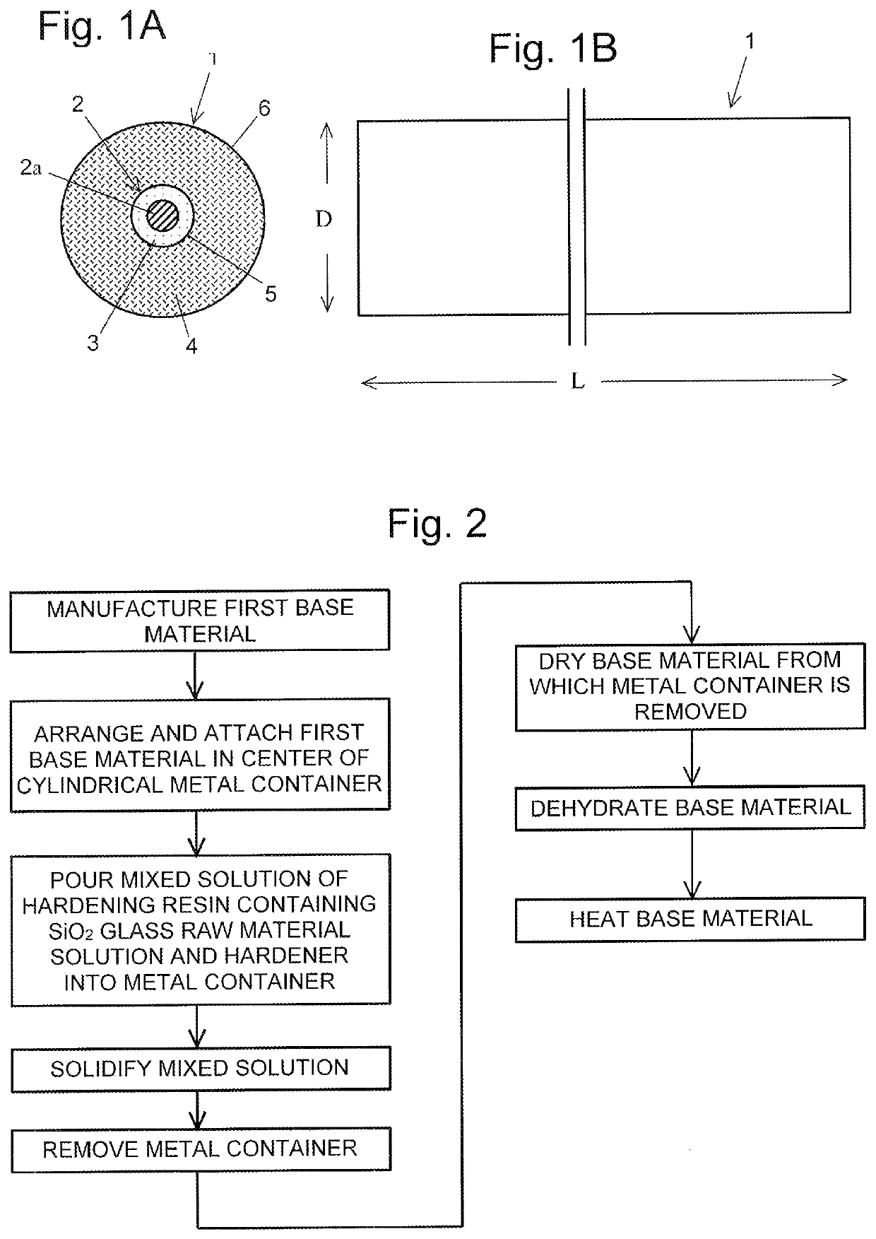
[0114]FIGS. 1A and 1B illustrate a first embodiment of an optical fiber base material of the present invention.

[0115]FIG. 1A is a front cross sectional view of the optical fiber base material, and FIG. 1B is a side view of the optical fiber base material. An optical fiber base material 1 of FIGS. 1A and 1B includes: a SiO2 glass rod 2 containing SiO2 glass for a core (hereinafter, referred to as glass rod 2); and a SiO2 cladding layer 4 that covers the outer periphery of the glass rod 2. The center of the glass rod 2 is made of a SiO2 glass layer 2a to which GeO2 is added within a range of 5 weight % to 25 weight %, and the outer periphery of the glass rod 2 is made of a SiO2 glass layer 3. The glass rod 2 is formed according to a method of the present invention.

[0116]The SiO2 cladding layer 4 is obtained by: pouring a quartz glass solution containing a hardening resin, and a hardener into a metal container; solidifying the quartz glass solution and the hardener through a self-harde...

second embodiment

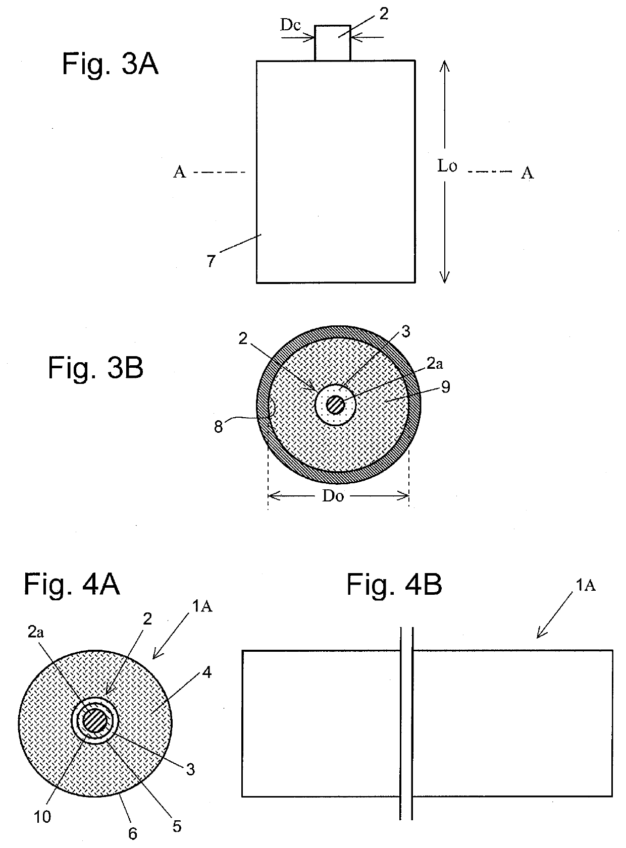
[0130]FIGS. 4A and 4B illustrate a second embodiment of the optical fiber base material of the present invention. FIG. 4A is a front cross sectional view of the optical fiber base material, and FIG. 4B is a side view of the optical fiber base material.

[0131]An optical fiber base material 1A of FIGS. 4A and 4B is an embodiment of a large-diameter optical fiber base material. The optical fiber base material 1A is manufactured using a metal container illustrated in FIGS. 5A and 5B. The glass rod 2 of the optical fiber base material 1A includes: the SiO2 layer 2a to which a GeO2 additive for enhancing a refractive index is added, in the center of the glass rod 2; a SiO2 layer 10 to which F is added, in the outer periphery of the SiO2 layer 2a; and the SiO2 glass layer 3 to which F is not added, in the outer periphery of the SiO2 layer 10. The SiO2 cladding layer 4 is formed in the outer periphery of the glass rod 2, using the metal container 7 illustrated in FIGS. 5A and 5B.

[0132]The me...

third embodiment

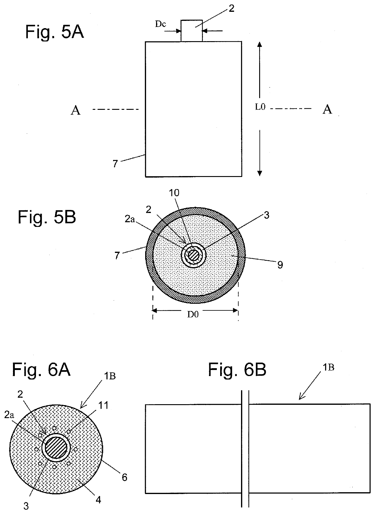
[0133]FIGS. 6A and 6B illustrate an embodiment of a hole assisted optical fiber base material of the present invention. FIG. 6A is a front cross sectional view of the optical fiber base material, and FIG. 6B is a side view of the optical fiber base material. An optical fiber base material 1B of FIGS. 6A and 6B is manufactured using: the first base material (glass rod 2) described in the first embodiment; the metal container 7 (see FIGS. 3A and 3B); and a plurality of stainless-steel metal rods (not illustrated) (each having a surface roughness of 0.03 μm or less). First, the first base material is arranged in the center of the metal container 7, and the plurality of stainless-steel metal rods are arranged at preset intervals in the outer periphery of the first base material. In this state, the mixed solution 9 of: the quartz glass solution containing the hardening resin; and the hardener is poured into the metal container 7. The mixed solution 9 is solidified through a self-hardenin...


PUM

PropertyMeasurementUnit
surface roughnessaaaaaaaaaa

Abstract

The present invention provides a method for manufacturing an optical fiber base material and an optical fiber base material, the method including: arranging a rod containing SiO2 family glass for core, in a container; pouring a SiO2 glass raw material solution for cladding layer and a hardener into the container, the glass raw material solution containing a hardening resin; solidifying the glass raw material solution through a self-hardening reaction; and then drying the solidified material and heating the solidified material in chlorine gas, to manufacture an optical fiber base material in which a SiO2 cladding layer is formed in an outer periphery of the rod containing SiO2 family glass for core.

Description

CROSS REFERENCE[0001]This is a divisional of the patent application Ser. No. 14 / 373,382, filed on Oct. 31, 2014, which is a national stage entry of PCT / JP2013 / 050720 filed on Jan. 17, 2013, which in turns claims the priority of JP2013-009382 filed on Jan. 19, 2012. All of the applications prior to this divisional are incorporated herein by reference.TECHNICAL FIELD[0002]The present invention relates to a base material for an optical fiber including a core part and a cladding part, and, more particularly, to a method for manufacturing an optical fiber base material having a special structure which includes a large number of empty holes, voids and the like, and to an optical fiber base material.BACKGROUND ART[0003]Along with a technical progress of optical fibers, optical fibers having special structures have been developed. Examples of such optical fibers having special structures are illustrated in FIGS. 18A-18C. FIG. 18A illustrates a hole assisted fiber, FIG. 18B illustrates a pho...

Claims


Application Information

Patent Timeline
Patent Type & Authority Applications(United States)
IPC IPC(8): C03B37/012C03B37/016
CPCC03B2203/04C03B37/01208C03B37/01205C03B2203/14C03B2203/34Y10T428/2944C03B2201/31Y10T428/294Y10T428/2964C03B2203/12C03B37/0122C03B2203/42Y10T428/2935C03B37/016C03B37/01282C03B2201/36C03B37/01262C03B37/01222
Inventor IMOTO, KATSUYUKIISHII, FUTOSHI
Owner KOHOKU KOGYO CO LTD
Why Eureka
Try Eureka