Camshaft adjuster

a camshaft adjuster and camshaft technology, applied in the direction of machines/engines, mechanical equipment, engine components, etc., can solve the problems of increasing the consumption affecting the operation of internal combustion engines, so as to achieve simple and cost-effective construction

Active Publication Date: 2019-07-16
SCHAEFFLER TECH AG & CO KG
View PDF30 Cites 0 Cited by
  • Summary
  • Abstract
  • Description
  • Claims
  • Application Information

AI Technical Summary

Benefits of technology

[0004]It is an object of the present invention to eliminate the deficiencies known from the prior art in a camshaft adjuster and to refine a camshaft adjuster which includes a central locking mechanism in such a way that the efficiency is increased and pressure peaks are minimized.
[0005]The present invention provides that the pressure medium supply includes an oil pump, a supply line, which connects the oil pump to at least one working chamber, and a hydraulic accumulator, which differs from the oil pump and the supply line. As a result, a smaller oil pump may be used, and the risk of an underpressure occurring in a working chamber of the camshaft adjuster and air being sucked into the system thereby is greatly reduced. Due to the valves integrated into the vanes of the rotor, a hydraulic pass through the rotor may be activated in a first switching position of the valves, so that a hydraulic compensation between the two working chambers is possible, which facilitates the rotation of the rotor into a central position. The oscillating torques of the camshaft acting upon the camshaft adjuster may thus move the rotor by conveying the pressure medium from the one working chamber into the particular other working chamber of the chamber. This means that an adjustment of the rotor may take place via the oscillating torques of the camshaft without having to convey pressure medium in one of the working chambers by the oil pump, or the pressure built up by the oil pump uniformly acting upon both working chambers of a chamber. However, if the two working chambers of a chamber are separated by placing the valves into a second switching position, the particular first working chambers or second working chambers are connected to the hydraulic accumulator, so that the pressure medium is able to subsequently flow into the particular enlarging working chamber during a rotation of the rotor induced by oscillating torques. This safely prevents an underpressure from occurring in a working chamber and thus air being sucked in.
[0006]According to one preferred specific embodiment, it is provided that the pressure medium in the hydraulic accumulator is stored under a higher pressure with respect to the ambient pressure. A subsequent flow of the pressure medium into the working chambers of the camshaft adjuster is facilitated thereby. In addition, a harmful underpressure may be even more reliably avoided thereby, since an earlier and faster subsequent flow of pressure medium occurs, due to the increased pressure in the hydraulic accumulator.

Problems solved by technology

Relatively large and heavy oil pumps are required for this purpose to generate a sufficient volume flow to completely fill the enlarging working chambers in the camshaft adjuster with oil.
If this does not take place, an underpressure may occur in the working chamber, whereby air is sucked into the camshaft adjuster.
Due to the compressibility of air, the rotor is then no longer sufficiently hydraulically clamped in the chambers, so that vibrations may occur, which may impair the operation of the internal combustion engine and increase the consumption of the internal combustion engine and increase wear on the camshaft adjuster.
However, the disadvantage of this approach is that no central locking mechanism is provided.

Method used


Image

  • Camshaft adjuster
  • Camshaft adjuster
  • Camshaft adjuster

Examples


Embodiment Construction

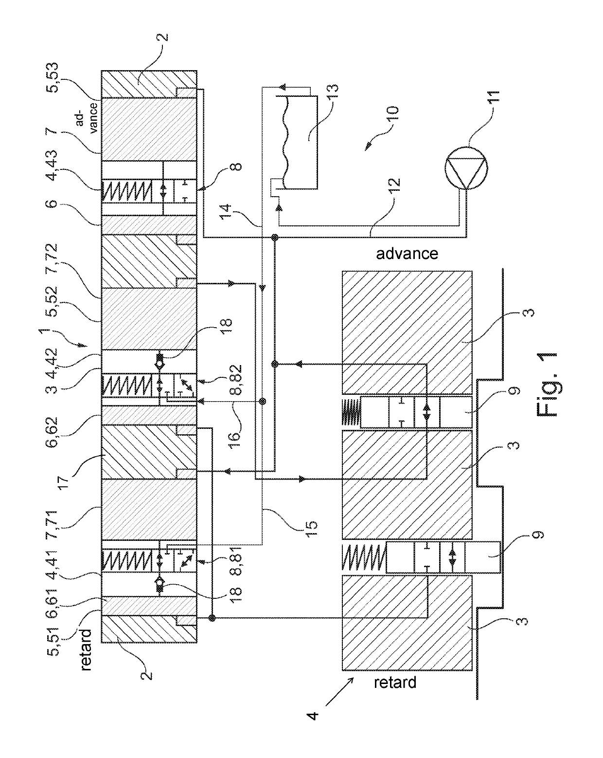
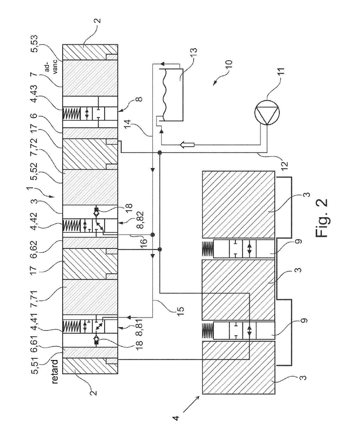
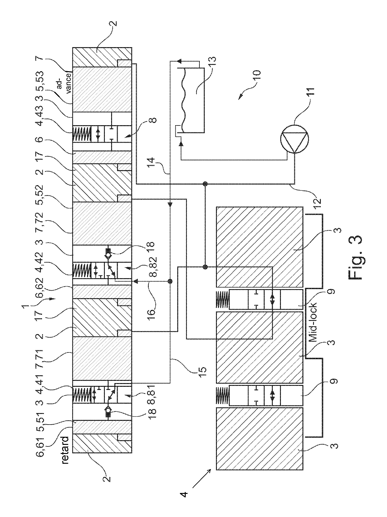
[0018]A camshaft adjuster 1 according to the present invention, including a stator 2 and a rotor 3, is illustrated in FIG. 1. Webs 17 are formed on stator 2, which divide an annular space between stator 2 and rotor 3 into chambers 5, 51, 52, 53. In principle, a rotor 3 having only one chamber 5 is possible, however three or more chambers 5, 51, 52, 53 are preferably formed on rotor 3, as illustrated in FIG. 1. Chambers 5, 51, 52, 53 between stator 2 and rotor 3 are each divided into two working chambers 6, 7 by a vane 4, 41, 42, 43 of rotor 3, particular working chambers 6 on the left of vane 4 of rotor 3 in the figures being referred to as first working chambers 6, 61, 62, and the working chambers on the right of vane 4 in the figures being referred to as second working chambers 7, 71, 72. Switchable valves 8, 81, 82 are formed in each of vanes 4, 41, 42, 43 of rotor 3, valves 8, 81, 82 each being adjustable between at least two switching positions. In a first switching position of...


PUM


Abstract

A camshaft adjuster including a stator, a rotor and a pressure medium supply, at least one chamber being formed on the stator, which is divided into two working chambers by at least one vane formed on the rotor or rotatably fixedly connected to the rotor is provided. A pressure medium is applicable to each of the two working chambers via the pressure medium supply in such a way that a pressure of the pressure medium may be increased in each of the working chambers to the extent that the pressure increase results in a rotation of the rotor. A switchable valve is formed in the vane of the rotor, which, in a first switching position of the valve, allows a flow of the pressure medium from a first working chamber through the vane into a second working chamber, in a second switching position the valve hydraulically separating the working chambers from each other. A locking element, which fixes the vane in a defined position with respect to the chamber, is designed to control an inflow or outflow of the pressure medium into or out of a working chamber. The pressure medium supply includes an oil pump, a supply line connecting the oil pump to at least one of the working chambers and a hydraulic accumulator, which differs from the oil pump and the supply line.

Description

[0001]The present invention relates to a camshaft adjuster for changing the control times of gas exchange valves on an internal combustion engine, including a stator, a rotor and including a pressure medium supply, at least one chamber being formed on the stator, which is divided into two working chambers by at least one vane formed on the rotor or rotatably fixedly connected to the rotor. A pressure medium is applicable to each of the two working chambers via the pressure medium supply in such a way that a pressure of the pressure medium in the particular working chamber may be increased to such an extent that the pressure increase results in a rotation of the rotor. A switchable valve is formed in the vane of the rotor, which, in a first switching position of the valve, permits the pressure medium to flow from a first working chamber, through the vane into a second working chamber, the valve hydraulically separating the working chambers from each other in a second switching positi...

Claims


Application Information

Patent Timeline
Patent Type & Authority Patents(United States)
IPC IPC(8): F01L1/344
CPCF01L1/3442F01L2001/34426F01L2001/34463F01L2001/34446F01L2001/34453F01L2001/34433
Inventor BOESE, OLAFTHIELEN, JOCHENDIETZ, JOACHIM
Owner SCHAEFFLER TECH AG & CO KG
Why Eureka
Try Eureka