
Internal combustion engine provided with turbocharger

a technology of internal combustion engine and turbocharger, which is applied in the direction of engine starters, machines/engines, gearing details, etc., can solve the problems of difficult to secure a large distance from the engine auxiliary to not only the turbocharger but also the exhaust pipe, and achieve the effect of improving the exhaust efficiency

Active Publication Date: 2019-07-30
HONDA MOTOR CO LTD
View PDF80 Cites 4 Cited by
  • Summary
  • Abstract
  • Description
  • Claims
  • Application Information

AI Technical Summary

Benefits of technology

[0006]According this arrangement, the leg pieces provided on the side of the exhaust pipe with respect to the support plate shield the heat from the exhaust pipe to the engine auxiliary, and therefore, heat reception by the engine auxiliary is suppressed. Because the leg pieces are arranged unevenly to provide a higher heat shielding performance on the side of the exhaust pipe than on the side of the compressor with respect to the support plate, the heat from the exhaust pipe can be blocked efficiently.
[0008]According this arrangement, the leg pieces can be easily arranged unevenly to provide a higher heat shielding performance on the side of the exhaust pipe than on the side of the compressor with respect to the support plate, whereby the heat from the exhaust pipe can be blocked efficiently.
[0010]According this arrangement, the leg pieces can be easily arranged unevenly to provide a higher heat shielding performance on the side of the exhaust pipe than on the side of the compressor with respect to the support plate, the heat transmitted from the exhaust pipe to the engine auxiliary can be reduced efficiently.
[0012]According this arrangement, the expansion wall contributes to reducing the heat transmitted from the exhaust pipe to the engine auxiliary.
[0016]According this arrangement, it is possible to efficiently reduce the heat transmitted from the catalytic converter, which has a relatively large volume, to the engine auxiliary.
[0020]According this arrangement, the exhaust pipes (upstream exhaust pipes) extending from the respective banks to the turbine can have a substantially same length, and this improves the exhaust efficiency.

Problems solved by technology

In a case where an internal combustion engine is disposed in a small space such as when the internal combustion engine is mounted on an automobile, it is often difficult to secure a large distance from an engine auxiliary to not only the turbocharger but also an exhaust pipe extending from the turbocharger to an exhaust outlet.

Method used


Image

  • Internal combustion engine provided with turbocharger
  • Internal combustion engine provided with turbocharger
  • Internal combustion engine provided with turbocharger

Examples


Embodiment Construction

)

[0029]In the following, an embodiment of an internal combustion engine to which the present invention is applied will be described with reference to the drawings.

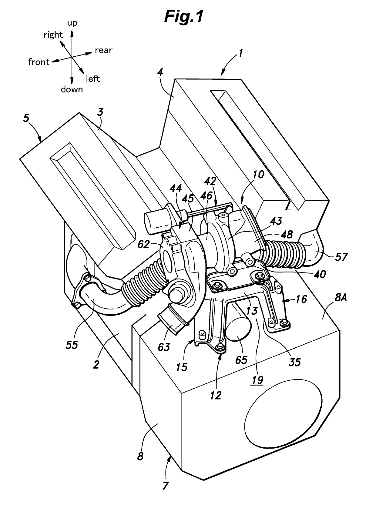
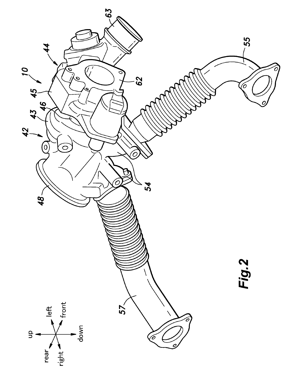
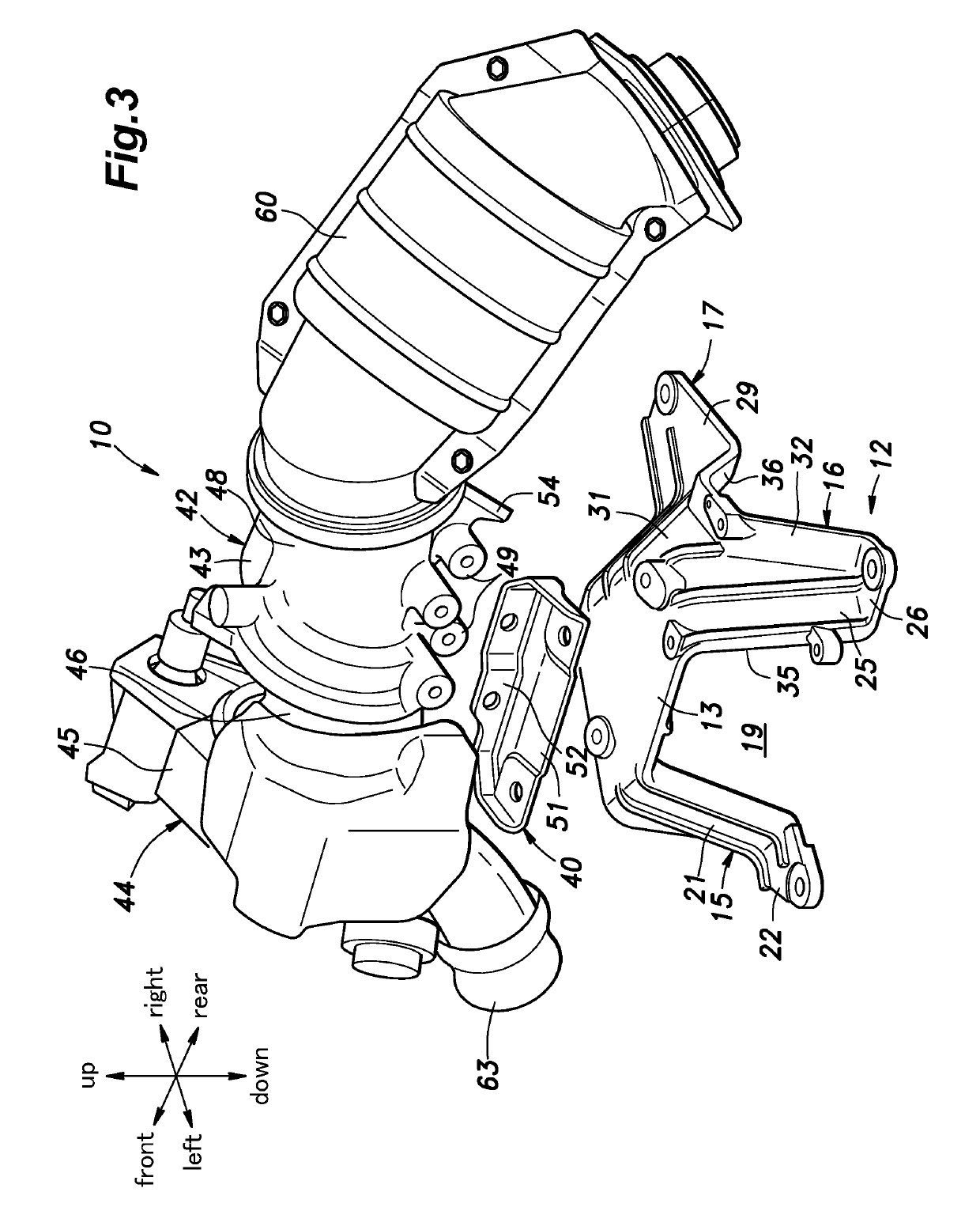
[0030]As shown in FIG. 1, an internal combustion engine 1 for an automobile consists of a transverse V-type engine, and has an engine main body 5 including a crankcase 2 and a front cylinder bank 3 and a rear cylinder bank 4 provided on top of the crankcase 2. The front cylinder bank 3 and the rear cylinder bank 4 each extend laterally (or in the left-right direction) and define a plurality of cylinders. The front cylinder bank 3 tilts forward about a laterally extending crankshaft, while the rear cylinder bank 4 tilts rearward about the crankshaft. The front cylinder bank 3 has a plurality of intake ports opening out in a rear surface thereof and connected to the respective cylinders and a plurality of exhaust ports opening out in a front surface thereof and connected to the respective cylinders. The rear cylinder bank 4 ...


PUM


Abstract

An internal combustion engine, includes: an engine main body; a structural member disposed around the engine main body; a bracket including a support plate and a plurality of leg pieces depending from the support plate and connected to the structural member; a turbocharger including a turbine and a compressor, the turbine being connected to a side of the support plate opposite to the structural member; an exhaust pipe connected to a central part of the turbine and extending in a direction away from the compressor; and an engine auxiliary disposed between the structural member and the support plate, wherein the leg pieces are arranged unevenly to provide a higher heat shielding performance on a side of the exhaust pipe than on a side of the compressor with respect to the support plate.

Description

TECHNICAL FIELD[0001]The present invention relates to an internal combustion engine provided with a turbocharger.BACKGROUND ART[0002]With regard to an internal combustion engine provided with a turbocharger, it is known to provide a pedestal on a side of an engine main body to support a turbocharger on the pedestal (see JP2016-191304A, for example). The turbocharger is mounted on an upper surface of a support plate constituting a part of the pedestal, and an air cooler (intercooler) is disposed below the support plate. In this configuration, the support plate prevents the heat generated by the turbocharger from being transmitted to the air cooler, and therefore, the turbocharger and the air cooler can be arranged close to each other.[0003]In a case where an internal combustion engine is disposed in a small space such as when the internal combustion engine is mounted on an automobile, it is often difficult to secure a large distance from an engine auxiliary to not only the turbocharg...

Claims


Application Information

Patent Timeline
Patent Type & Authority Patents(United States)
IPC IPC(8): F02B67/10F02N15/00F16H57/02F02B37/00F01N13/18F01N13/08F01N5/04F16H57/025F02B77/11F02B75/22F01N13/14F01N3/10
CPCF02B67/10F01N5/04F01N13/08F01N13/14F01N13/185F01N13/1805F01N13/1855F01N13/1861F01N13/1872F02B75/22F02B77/11F02N15/006F16H57/025F01N3/10F16H2057/0203F01N2260/20F01N2340/04F01N2340/06F01N2450/20F01N2450/24F02B37/00F02N11/00Y02T10/12
Inventor HIGO, YUTAKASEKIYA, NORITAKANOMOTO, SOICHIRO
Owner HONDA MOTOR CO LTD
Learn More