Variable stator vane mechanism

a stator vane and variable technology, applied in the manufacture of non-positive displacement fluid engines, pump components, engine components, etc., can solve the problems of high cost, increased inability to use rollers which will easily wear, etc., to achieve the effect of increasing the frequency of roller replacement, high cost, and complicated structur

Active Publication Date: 2019-07-30
KAWASAKI HEAVY IND LTD
View PDF30 Cites 6 Cited by
  • Summary
  • Abstract
  • Description
  • Claims
  • Application Information

AI Technical Summary

Benefits of technology

[0009]However, in the cases of the variable stator vane mechanisms shown in Patent Documents 1 and 2, a ring that supports stator vanes is movably supported by rollers such that the mounting angle of the stator vanes can be adjusted. Accordingly, the structure is complicated, resulting in high costs, wear of the rollers due to aged deterioration would be confirmed, and the frequency of replacement of the rollers is increased.
[0010]An object of the present invention is to provide a variable stator vane mechanism, for an axial flow compressor, which is excellent in durability, has a simple structure, and is realized at low cost.

Problems solved by technology

Accordingly, the structure is complicated, resulting in high costs, wear of the rollers due to aged deterioration would be confirmed, and the frequency of replacement of the rollers is increased.
In addition, rollers which will easily wear are not used, and the friction pad whose coefficient of friction is small is used.

Method used


Image

  • Variable stator vane mechanism
  • Variable stator vane mechanism
  • Variable stator vane mechanism

Examples


first embodiment

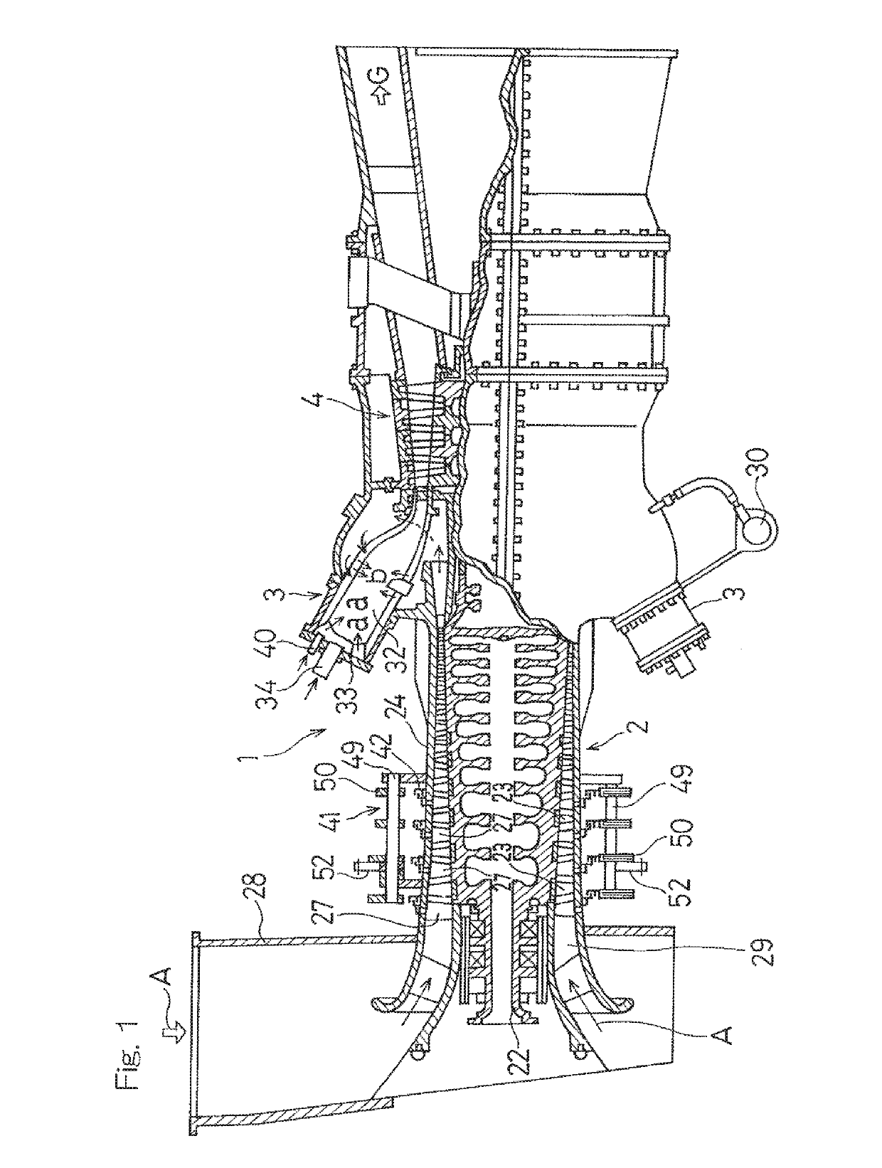
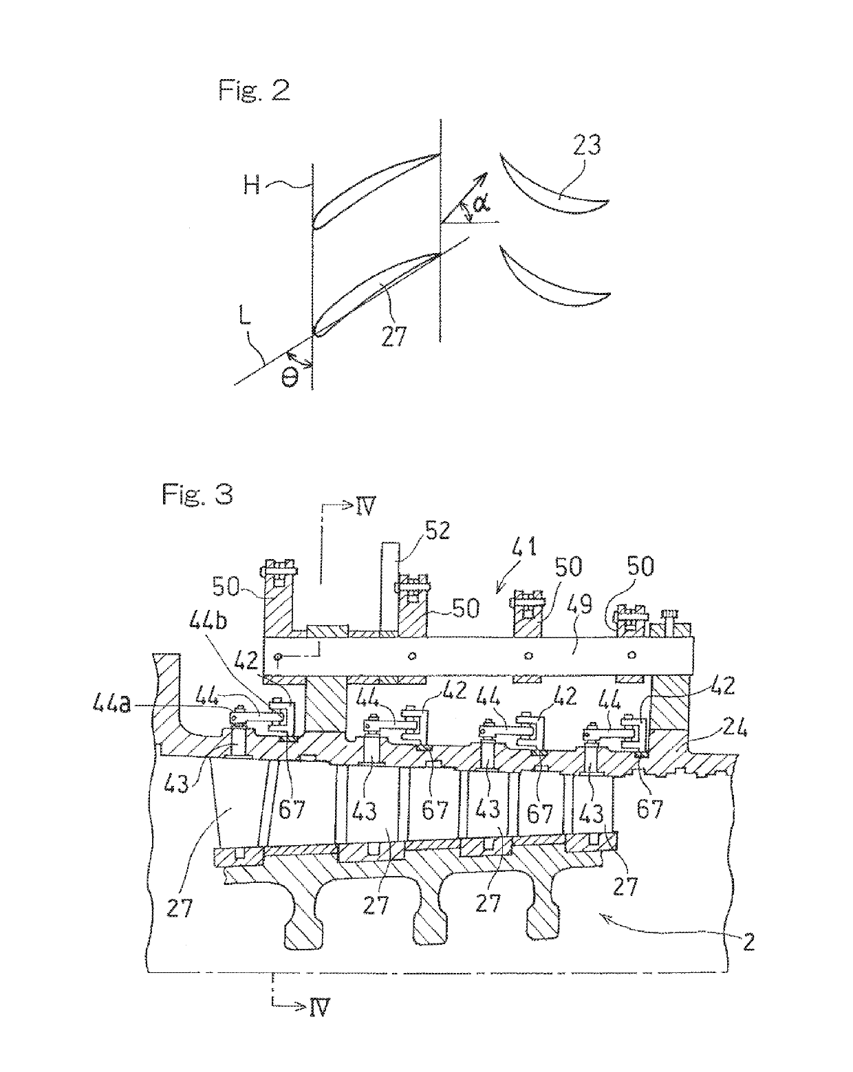
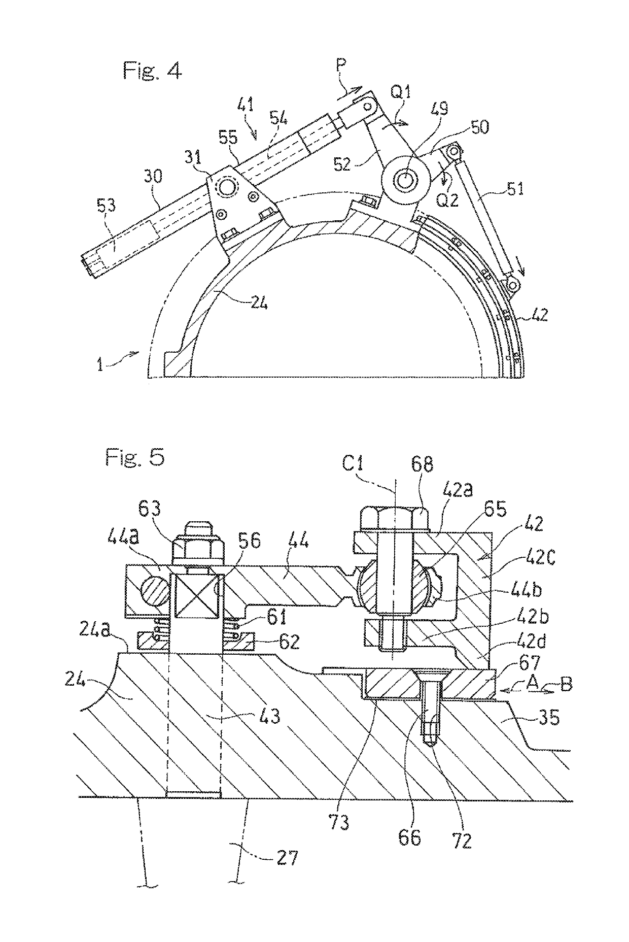
[0036]Next, the variable stator vane mechanism 41 will be described with reference to FIG. 3 which is a longitudinal cross-sectional view showing one portion thereof, and FIG. 4 which is a cross-sectional view along a line IV-IV shown in FIG. 3. As shown in FIG. 3, in this embodiment, assuming that a large number of stator vanes 27 arranged along the circumferential direction of the casing 24 of the axial flow compressor 2 form one stage, the mounting angles θ of the stator vanes 27 in four stages are adjusted in an interlocking manner. On an outer side of the casing 24, an annular rotation ring 42 having a U-shaped cross section is rotatably provided at a position close to the arrangement positions of the stator vanes 27 of each stage, along the circumferential direction thereof. Each of the stator vane 27 includes a central shaft 43 having a distal end (an upper end on the sheet of FIG. 3) to which a proximal end portion 44a of an arm 44 is fitted and fixed. The rotation ring 42 ...

second embodiment

[0046]FIG. 9 and FIG. 10 are front views each showing a As shown in FIG. 9, the friction pad 67 is mounted at a position between the spherical bearings 65, 65 in the casing 24, by means of the fastening members 66 such as bolts. Under a head portion of the shaft support member 68, a rotation prevention plate 77 which prevents rotation, in conjunction with an adjacent shaft support member 68, is mounted.

[0047]As shown in FIG. 10, the rotation ring 42 is formed with a tool insertion hole 75 in the form of a long hole elongated in the circumferential direction so as to penetrate the rotation ring 42, at a position that is opposed to the fastening members 66 and that is on the radially outer side relative to the fastening members 66. By inserting a tool such as a screwdriver from the tool insertion hole 75, the fastening members 66 are fasten or loosened. In a case where the friction pad 67 or / and the shim 73 is / are to be replaced when the friction pad 67 has worn, the fastening member...


PUM


Abstract

To provide a variable stator vane mechanism, for an axial flow compressor, which is excellent in durability, has a simple structure, and is realized at low cost. The variable stator vane mechanism for adjusting a mounting angle of a stator vane of an axial flow compressor includes: an arm coupled to the stator vane; a rotation ring coupled to one end portion of the arm and located at an outer surface of a casing of the axial flow compressor; a driving machine configured to rotate the rotation ring to cause the stator vane to pivot via the arm; and a friction pad mounted on the casing. The rotation ring is in frictional contact with the friction pad.

Description

CROSS REFERENCE TO THE RELATED APPLICATION[0001]This application is a continuation application, under 35 U.S.C. § 111(a), of international application No. PCT / JP2014 / 081170, filed Nov. 26, 2014, which claims priority to Japanese patent application No. 2013-262426, filed Dec. 19, 2013, the disclosure of which are incorporated by reference in their entirety into this application.BACKGROUND OF THE INVENTION[0002]Field of the Invention[0003]The present invention relates to a variable stator vane mechanism which adjusts the mounting angle of stator vanes of an axial flow compressor which is used in a gas turbine engine, a turbo refrigerator, or the like.[0004]Description of Related Art[0005]In a gas turbine engine, an axial flow compressor is used in order to compress gas. In the gas turbine engine, suctioned air is compressed by an axial flow compressor so as to have high pressure, and then is guided to a combustor. High-temperature and high-pressure gas burnt in the combustor is recove...

Claims


Application Information

Patent Timeline
Patent Type & Authority Patents(United States)
IPC IPC(8): F01D17/16F04D29/56
CPCF01D17/162F04D29/563F05D2250/40
Inventor IKEGUCHI, TAKUYANAKAYAMA, KENTARO
Owner KAWASAKI HEAVY IND LTD
Why Eureka
Try Eureka