Fiber application head with a specific application roll

a fiber and application head technology, applied in the direction of liquid surface applicators, coatings, etc., can solve the problems of complex structure and implementation of segmented metallic rolls, and the tendency of flexible rolls to deteriorate rapidly, so as to achieve simple design and implementation

Inactive Publication Date: 2019-08-06
CORIOLIS GRP
View PDF134 Cites 0 Cited by
  • Summary
  • Abstract
  • Description
  • Claims
  • Application Information

AI Technical Summary

Benefits of technology

[0011]The purpose of embodiments of the present invention is to propose a solution intended to overcome the aforementioned drawbacks, which makes it possible in particular to process a wide variety of resins, both thermosetting and thermoplastic, with a compaction substantially uniform over the applied band, and which is simple in design and implementation.
[0019]This rotational drive of the roll ensures a more efficient and homogeneous cooling of the roll between two layup trajectories, and thus makes it possible to limit, or even eliminate, overheating of the application roll, in particular in the case of a flexible roll.
[0025]According to one embodiment, the application roll comprises a rigid central tube by which the roll is mounted to rotate on a support structure of the machine, for example in a removable manner via assembly parts, and a cylinder made of a supple or flexible material, elastically deformable, assembled coaxially on the central tube, possibly having an anti-adhesive layer. The cylinder of flexible material allows the compacting roll to adapt itself to the variations in curvature of the application surface and thus to apply a pressure substantially uniform over the whole of the laid band. The cylinder is for example an elastomer, in particular a silicone. The drive system according to the invention is proven to be particularly advantageous in the case of a flexible roll.
[0033]According to one embodiment, the heating system is activated before each layup trajectory, when the roll is not in contact with the application surface, in particularly during the link trajectory between two layup trajectories, in order to guarantee a sufficient heating from the beginning of the layup trajectory. This embodiment is particularly suitable in the case of an infrared heating system, particularly for heating dry fibers or fibers pre-impregnated with thermoplastic resin, the drive means making it possible to avoid the overheating of the roll by the heating system.

Problems solved by technology

These segmented metallic rolls have proven however to be complex in structure and implementation.
Despite these cooling systems, the flexible rolls can have the tendance to deteriorate rapidly in the case of the use of thermoplastic resins.

Method used


Image

  • Fiber application head with a specific application roll
  • Fiber application head with a specific application roll
  • Fiber application head with a specific application roll

Examples


Embodiment Construction

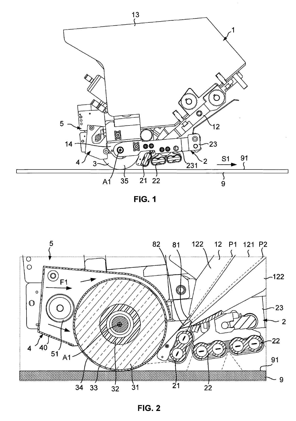
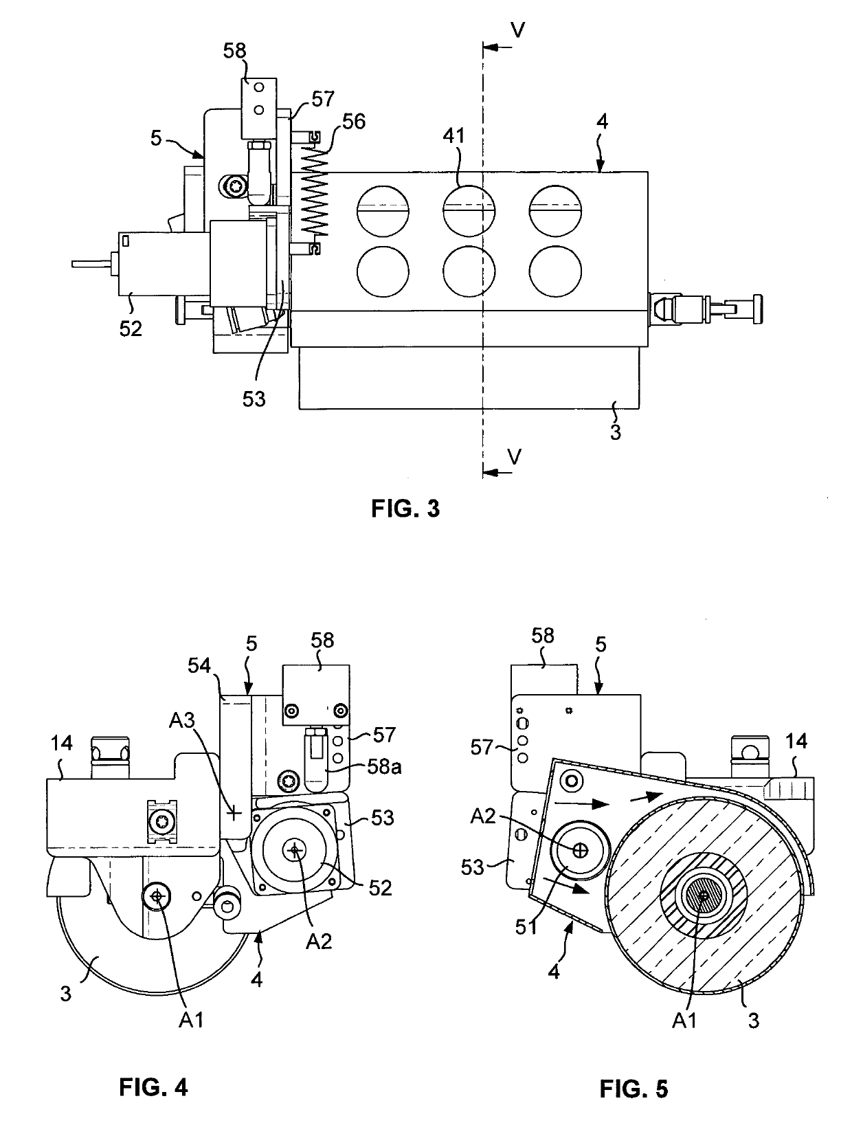
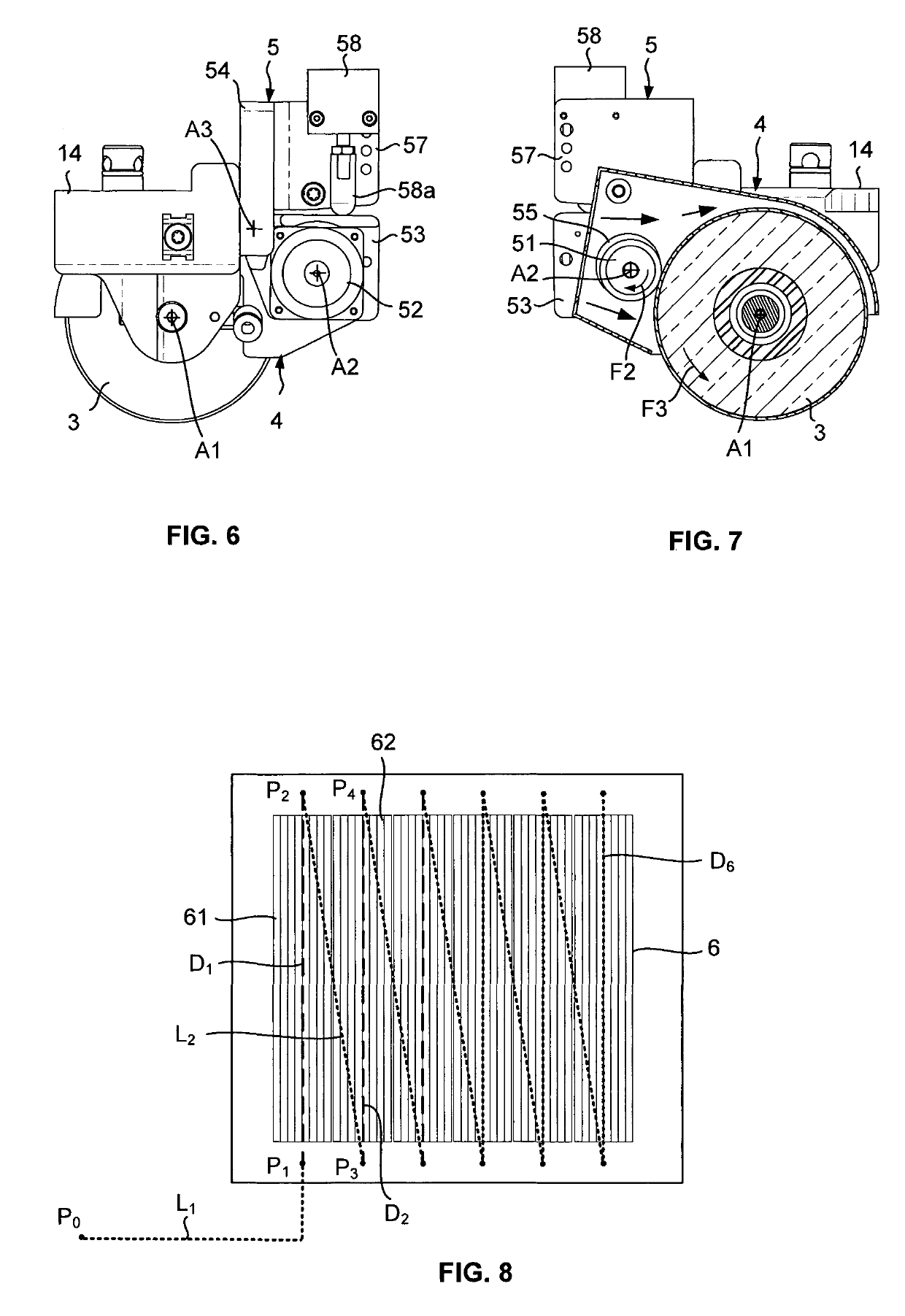
[0041]FIGS. 1 to 5 illustrate a fiber placement head 1 equipped with a drive system 5 according to embodiments of the invention, enabling the automatic layup by contact onto the application surface 91 of a mold 9 of bands formed by several fibers, by relative movement of the head in relation to the mold via a displacement system.

[0042]The head 1 comprises a compacting roll 3, a main guide system 12 for guiding the fibers in the direction of the roll in the form of two layers of fibers, in order to form a band of fibers in which the fibers are laid substantially edge to edge. With reference to FIG. 2, the head comprises for example a main guide system such as described in the aforementioned patent document, comprising first guide channels and second guide channels in which pass respectively the first fibers 81 of the first layer and the second fibers 82 of the second layer. The first channels and the second channels are arranged in staggered rows, along two guide planes, shown schema...


PUM

PropertyMeasurementUnit
temperaturesaaaaaaaaaa
melting temperatureaaaaaaaaaa
temperatureaaaaaaaaaa

Abstract

The invention relates to a fiber application head for manufacturing composite material pars and to a corresponding manufacturing method, said head including:an application roll for applying a band formed of one or more fibers onto an application surface;a main guide system for guiding at least one fiber towards said application roll;a heating, system capable of emitting thermal radiation towards the band just before application by the application roll;a cooling system capable of cooling, the application roil from the outside, such as a gas flow; anda drive system capable of rotating the application roll when the roll is not in contact with the application surface.

Description

RELATED CASES[0001]The present application is a National Phase entry of PCT Application No. PCT / FR2016 / 000057, filed Mar. 24, 2016, which claims priority from FR Patent Application No. 1500676, filed Apr. 1, 2015, which applications are hereby incorporated by reference in their entireties.TECHNICAL FIELD[0002]The present invention relates to a fiber application head for a fiber application machine for the production of composite material parts, and more particularly to a so-called fiber placement head equipped with a specific application roll. The present invention also relates to a method for manufacturing composite material parts by means of a corresponding application head.BACKGROUND ART[0003]There are known fiber application machines, commonly called fiber placement machines, for the application by contact onto a laying up tool, such as a male or female mold, of a wide band formed of several continuous flat fibers, of ribbon type, dry or impregnated with thermosetting or thermop...

Claims


Application Information

Patent Timeline
Patent Type & Authority Patents(United States)
IPC IPC(8): B29C70/38B05D7/00B29C35/08B29C35/16
CPCB05D7/52B29C35/0805B29C70/384B29C70/388B29C2035/1658B29C2035/0822B29C2035/0838
Inventor LEBORGNE, OLIVIER
Owner CORIOLIS GRP
Why Eureka
Try Eureka