
Method of two-stage FRM filter

a design method and filter technology, applied in the direction of impedence networks, digital technique networks, electrical equipment, etc., to achieve the effect of reducing the complexity of narrow-band fir filters and reducing power consumption

Active Publication Date: 2019-08-06
SHANDONG UNIV
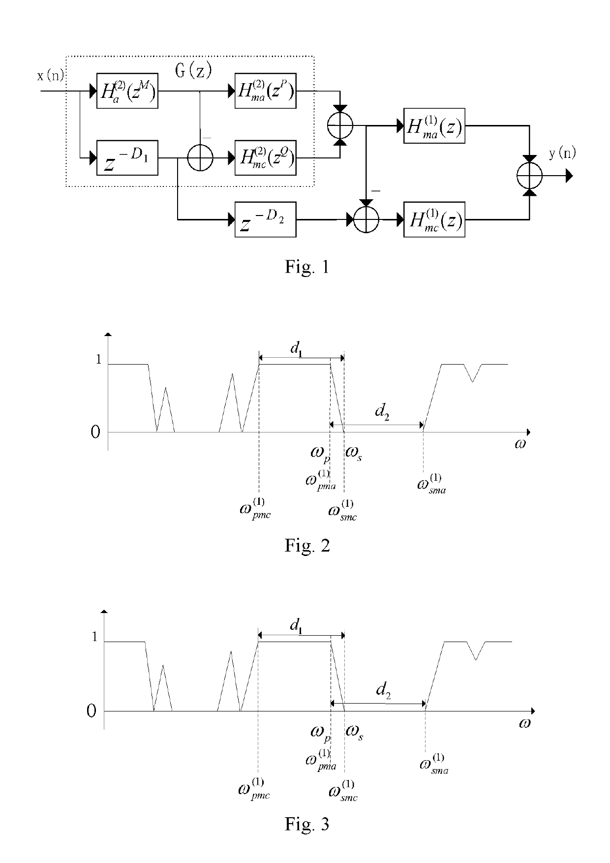
View PDF2 Cites 0 Cited by
  • Summary
  • Abstract
  • Description
  • Claims
  • Application Information

AI Technical Summary

Benefits of technology

The improved design reduces the complexity of narrow-band FIR filters, leading to lower power consumption in hardware implementation and allowing for a more efficient hardware structure.

Problems solved by technology

The satisfaction of the equation (3) leads to a direct problem that the second-stage output must be a periodic amplitude response.

Method used


Image

  • Method of two-stage FRM filter
  • Method of two-stage FRM filter
  • Method of two-stage FRM filter

Examples


example 1

[0156]The specific specifications of a filter having an extremely narrow transition band are as follows: ωp=0.6π, ωs=0.602π, δp=0.01, δs=0.01. By using the present design method, the final results are as follows: Na=28, Nma2=20, Nmc2=16, Nma=17, Nmc=29. The three interpolation factors M, P, Q are 69,9,9, respectively, which fall into Case B type: Casep=B, and Caseq=B. The number of multipliers is 59 with a group time delay being 1070.5. The passband and stopband ripples are 0.01 and 0.00999, respectively. Comparison of results of the method of the present invention with those of other existing methods is as shown in Table IX.

[0157]

TABLE IXResults of Designing Filter Using Various Methods inExample 1 And Comparison ThereofTotalGroupNumber OfTimeMethodMultipliersDelayConventional921105two-stage FRMSFFM-FRM case A861638.5SFFM-FRM case B842150.5Serial-masking FRM831016Non-periodical FRM551214Improved method591070.5

[0158]As can be seen from Table IX, when compared with the conventional t...


PUM


Abstract

An improved design method of a two-stage FRM filter includes the following steps: constructing an improved two-stage FRM filter; calculating passband and stopband edge parameters of a prototype filter, passband and stopband edge parameters of a second-stage masking filter and passband and stopband edge parameters of a first-stage masking filter in Case A and Case B, respectively; calculating the complexity of the FRM filter according to the obtained parameters, and finding out one or more sets [M, P, Q] having the lowest complexity within a search range; and optimizing the improved FRM filter. The improved design method of a two-stage FRM filter has the following beneficial effect: as compared to a conventional design method of a two-stage FRM filter, the complexity of a narrow-band FIR (Finite Impulse Response) filter can be reduced through design using the improved method, and power consumption is thus reduced in hardware implementation.

Description

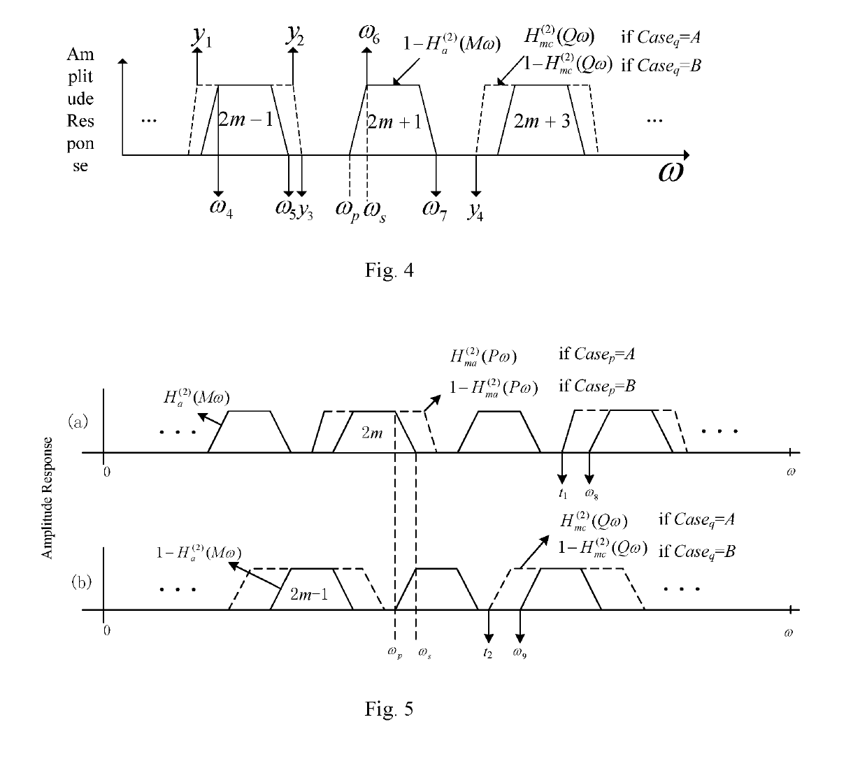
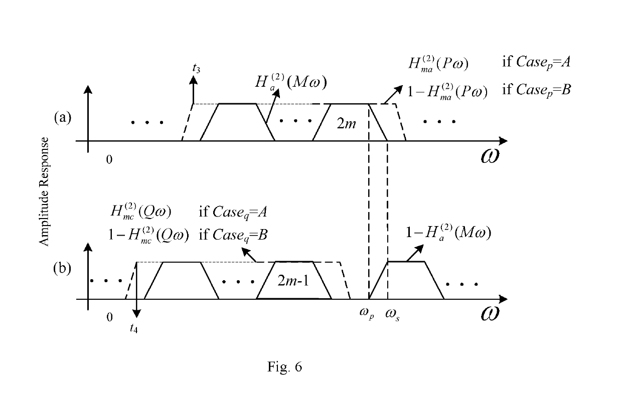
FIELD OF THE INVENTION[0001]The present invention relates to an improved design method of a two-stage FRM filter.BACKGROUND OF THE INVENTION[0002]Frequency response masking (FRM) is an efficient method for designing an FIR (Finite Impulse Response) filter having a narrow transition band characteristic. When a filter has a narrow transition band, multi-stage FRM may be utilized to further reduce its complexity.[0003]A filter is composed of a prototype filter Ha(z) and two masking filters Hma(z), Hmc(z). The transition band of the filter is provided by an interpolation filter Ha(zM) or its complement[0004](z-M⁡(Na-1)2-Ha⁡(zM))where M is an interpolation factor for Ha(z). The purpose of using two masking filters Hma(z) and Hmc(z) is to remove unnecessary periodic sub-bands.[0005]Two-stage FRM filters are widely used in practice. The structure of a two-stage FRM filter is as shown in FIG. 2. A transition band shaping filter is represented by G(z). A constraint condition for interpolatio...

Claims


Application Information

Patent Timeline
Patent Type & Authority Patents(United States)
IPC IPC(8): H03H17/02H03H17/06
CPCH03H17/06H03H17/02
Inventor WEI, YINGHUANG, SHAOGUANG
Owner SHANDONG UNIV
Learn More