
Linear motion guide unit

a technology of motion guide unit and guide surface, which is applied in the direction of sliding contact bearings, mechanical equipment, manufacturing tools, etc., can solve the problems of deformation of guide surfaces, failure to achieve smooth roller circulation, failure to smoothly pass, etc., to achieve high accuracy, prevent sliding resistance variations, and high accuracy

Active Publication Date: 2019-08-13
NIPPON THOMPSON
View PDF5 Cites 1 Cited by
  • Summary
  • Abstract
  • Description
  • Claims
  • Application Information

AI Technical Summary

Benefits of technology

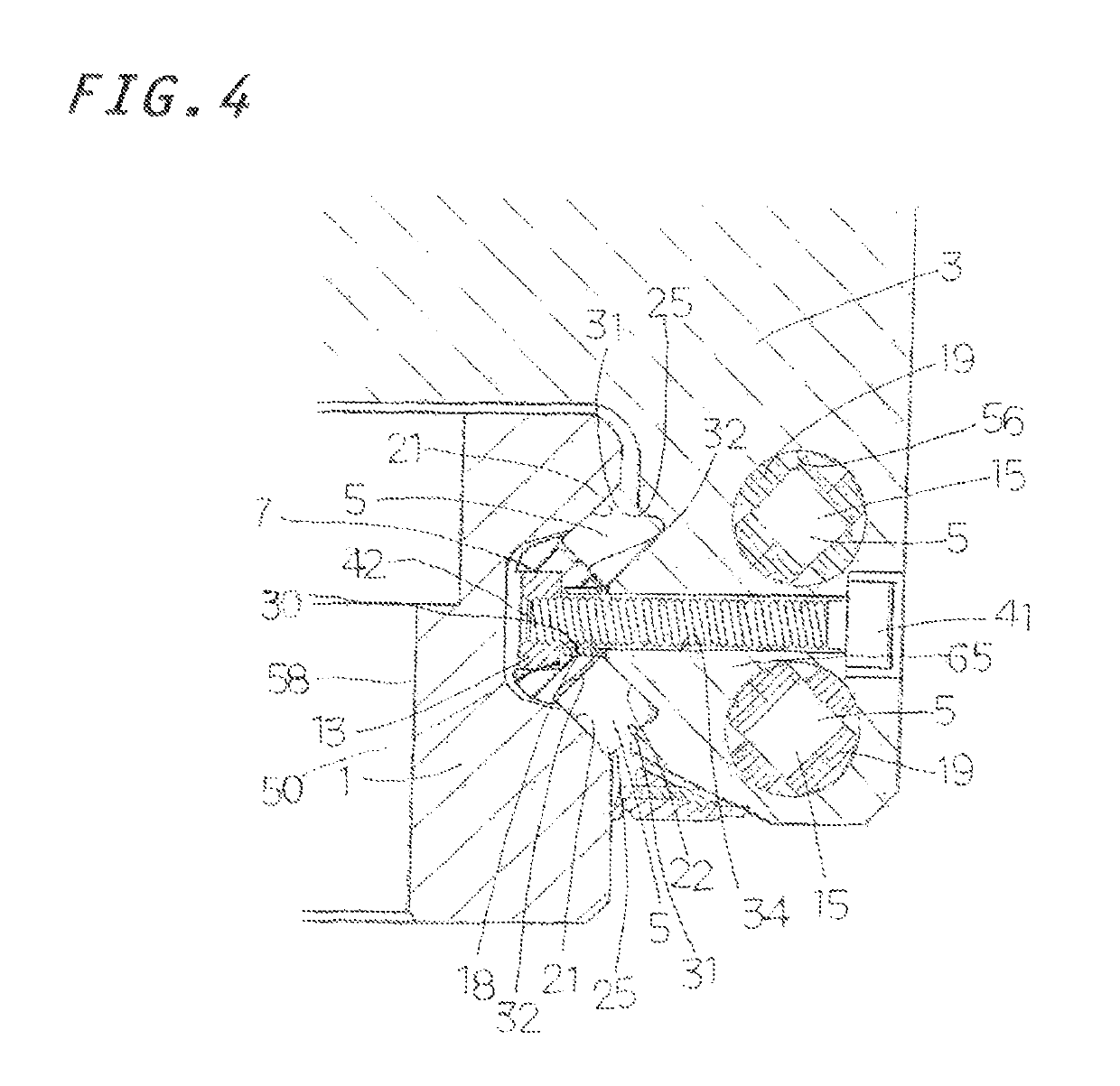
[0018]In the linear motion guide unit of the present invention, as mentioned above, in order to avoid possible deformation of the retainer member made of resin and constituting the retainer plate as a result of subjection to tightening forces of the fastening bolts, the frame members made of a metal are disposed in the retainer member at screwing positions, and the retainer plate is fixed to the carriage via the frame members. Since the tightening forces of the fastening bolts are not directly applied to the retainer member, there can be restrained deformation of the retainer member, which could otherwise result from screwing. That is, according to the present linear motion guide unit, since the tightening forces (axial forces) of the bolts are not directly applied to the retainer member, there can be restrained deformation, such as swelling, distortion, or crushing, of the retainer member, which could otherwise result from screwing; thus, the guide surfaces of the retainer member can be maintained as normal guide surfaces at all times. As a result, deformation, such as swelling, distortion, or crushing, of the guide surfaces of the retainer member of the retainer plate is prevented, so that interference between end surfaces of the rollers and the guide surfaces of the retainer member of the retainer plate can be restrained, and variations in sliding resistance can be prevented. Since the retainer member of the retainer plate is free from deformation and can be disposed with high accuracy, the retainer plate can be attached to the carriage with high accuracy, and smooth circulation of the rollers can be implemented.

Problems solved by technology

Meanwhile, a conventional large-sized roller-type linear motion guide unit has in some cases involved the following problem: in the case of fixing a retainer plate made of resin to a carriage by tightening fastening bolts with strong tightening torque, tightening forces (axial forces) of the bolts are applied directly to the retainer plate and cause deformation of the guide surfaces; as a result, for example, the guide surfaces swell to thereby narrow load-carrying races between a guide rail and the carriage, resulting in a failure to attain smooth circulation of rollers.
If the fixing band excessively presses the retainer plate toward the carriage, the following problem may arise: the retainer plate is deformed to thereby reduce the dimension between the guide surfaces of the load-carrying race; as a result, the guide surface of the retainer plate and the end surface of a roller interfere with each other; accordingly, the roller fails to smoothly pass, and sliding resistance increases.
Accordingly, a similar problem may arise as in the case of the above-mentioned large-sized roller-type linear motion guide unit.

Method used


Image

  • Linear motion guide unit
  • Linear motion guide unit
  • Linear motion guide unit

Examples


Embodiment Construction

[0035]A linear motion guide unit according to the present invention is applicable to relative sliding members used in various types of apparatus such as machine tools, semiconductor fabrication systems, and precision measuring apparatus.

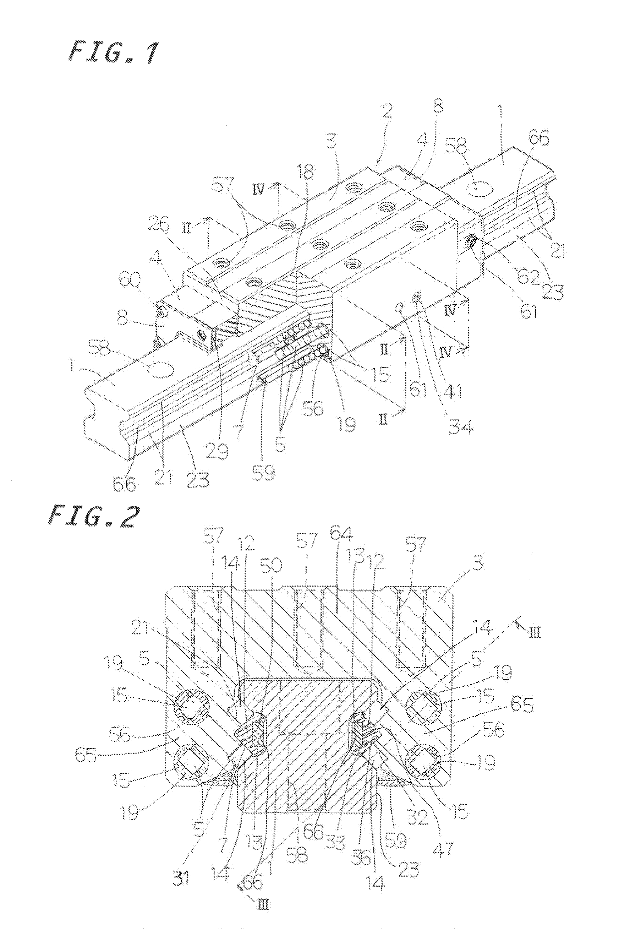
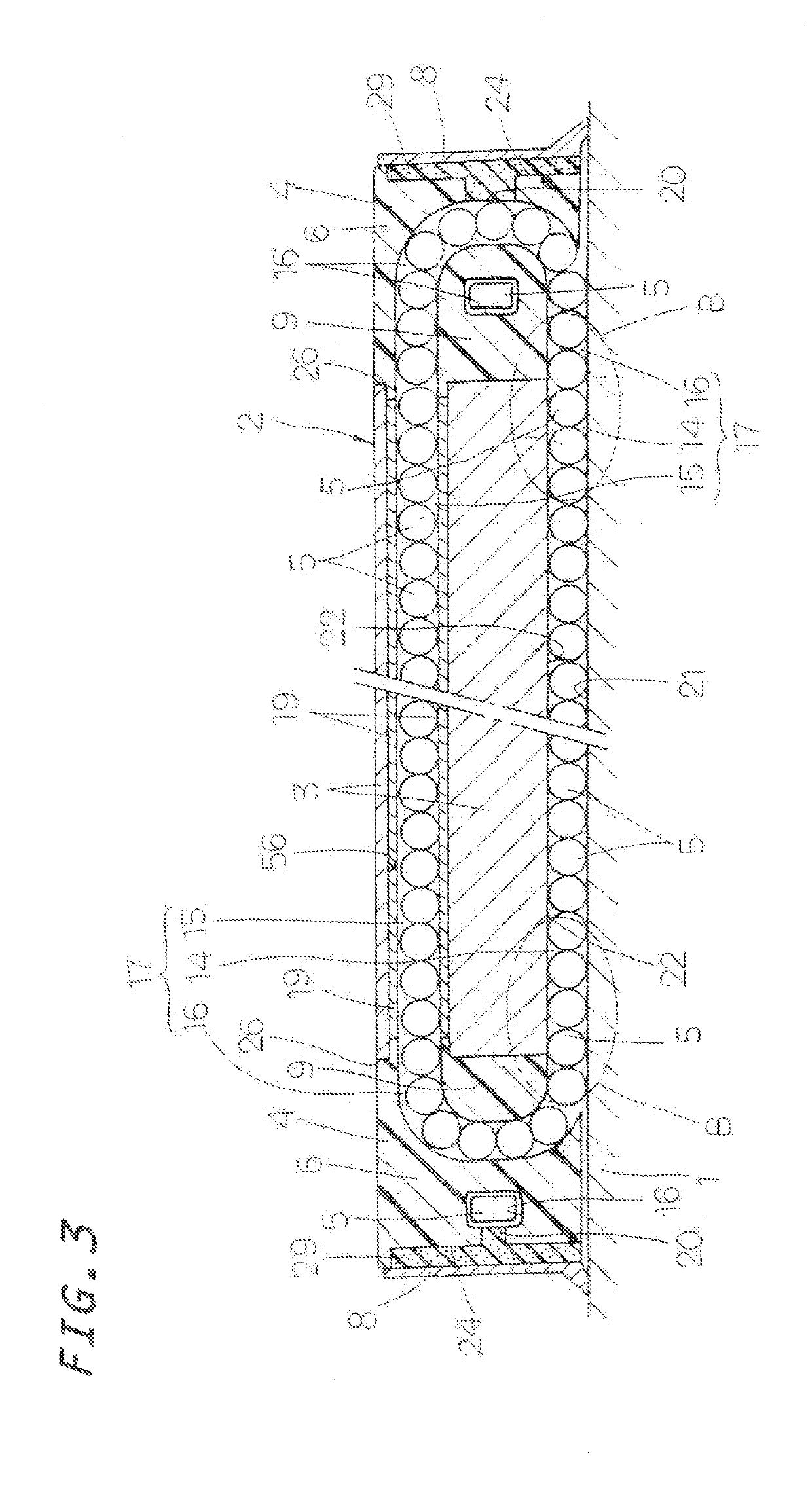
[0036]An embodiment of the linear motion guide unit according to the present invention will next be described with reference to the drawings. The members of FIG. 1 to FIGS. 12(a) and 12(b) which are identical to those of FIG. 15 and FIGS. 16(a) to 16(c) are denoted by the same reference numerals. As shown in FIGS. 1 to 4, the linear motion guide unit according to the present invention generally includes a guide rail 1 having raceway surfaces 21 (first raceway surfaces) extending in the longitudinal direction on respective longitudinal sides 23, and a slider 2 which has raceway surfaces 22 (second raceway surfaces) facing the respective raceway surfaces 21 as a result of its wing portions 65 straddling the guide rail 1 and which slides in relation to ...


PUM


Abstract

In the linear motion guide unit, a retainer plate for retaining rolling elements, or rollers, is prevented from deformation so as to smoothly guide the rollers. The retainer plate is composed of a retainer member, frame members fitted into respective through holes formed in the retainer member, and a fixing member disposed in a longitudinally extending recess of the retainer member. The frame members form a predetermined gap between the fixing member and a carriage. Tightening forces of fastening bolts are not applied to the retainer member, thereby avoiding deformation of the retainer member.

Description

FIELD OF THE INVENTION[0001]The present invention relates to a linear motion guide unit having retainer plates for retaining rollers rolling in load-carrying races, along raceway surfaces of a slider.BACKGROUND OF THE INVENTION[0002]In a conventionally known linear motion guide unit, retainer means for retaining cylindrical rollers is snap-on fixed to a slider to thereby increase the rated load of the slider. In the linear motion guide unit, a retainer plate is disposed between the cylindrical rollers disposed along an upper raceway surface of a carriage and the cylindrical rollers disposed along a lower raceway surface of the carriage. A holder portion of a fixing band is engaged with an engagement groove of the retainer plate and with engagement grooves of end caps. Engagement beaks at the ends of bend portions of the fixing band are engaged with respective engagement holes formed in the end caps. The retainer means for retaining the cylindrical rollers is incorporated in the slid...

Claims


Application Information

Patent Timeline
Patent Type & Authority Patents(United States)
IPC IPC(8): F16C29/06F16C29/00F16C17/24B23Q1/40B23Q1/01
CPCF16C29/005F16C17/246F16C29/065F16C29/0607F16C2370/00B23Q1/017B23Q1/40F16C29/0604F16C29/0628F16C29/063F16C29/0676
Inventor NAGAO, SHOJIHAYASHI, TOMOYUKIMIURA, MASAHIRO
Owner NIPPON THOMPSON
Learn More