Conductive detonating cord for perforating gun

a perforating gun and conductive technology, applied in the direction of explosive charges, fluid removal, borehole/well accessories, etc., can solve the problems of increased assembly cost, additional assembly steps and tim

Active Publication Date: 2019-08-20
DYNAENERGETICS
View PDF41 Cites 15 Cited by
  • Summary
  • Abstract
  • Description
  • Claims
  • Application Information

AI Technical Summary

Problems solved by technology

The use of multiple wires often requires additional assembly

Method used


Image

  • Conductive detonating cord for perforating gun
  • Conductive detonating cord for perforating gun
  • Conductive detonating cord for perforating gun

Examples


Embodiment Construction

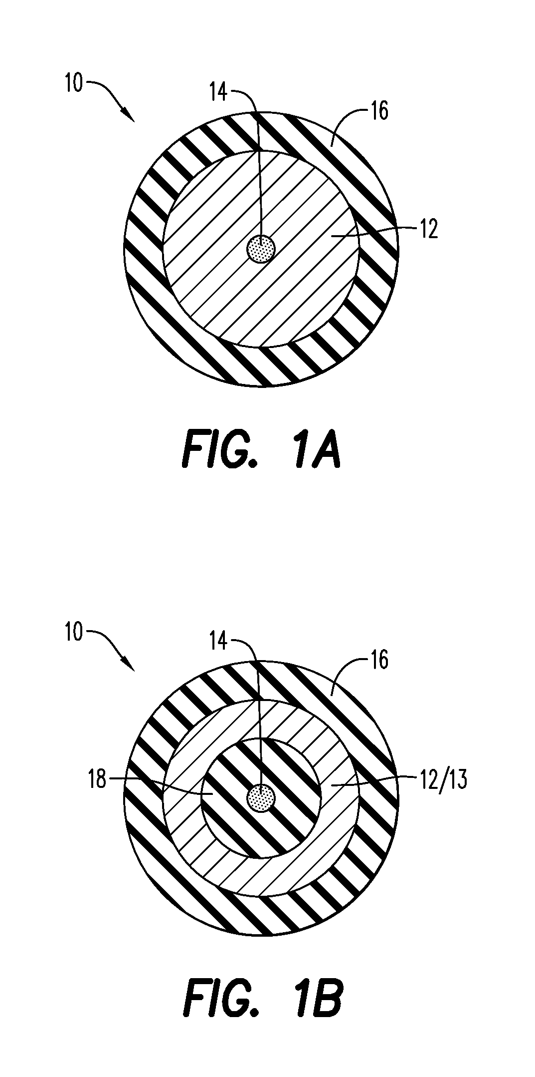
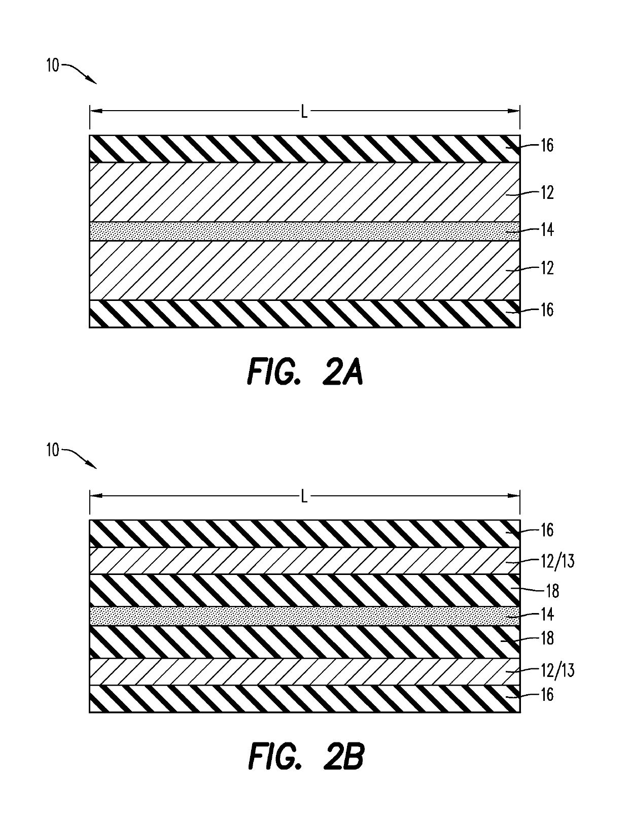
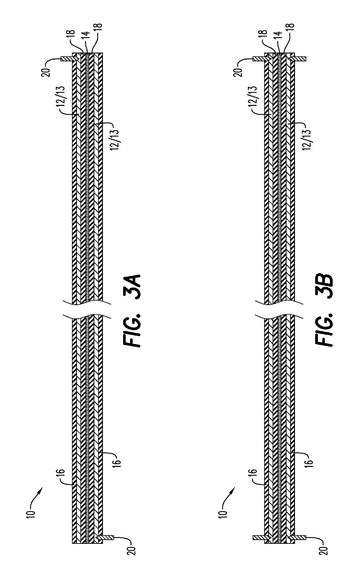
[0007]According to an aspect, the present embodiments may be associated with a detonating cord for using in a perforating gun. The detonating cord includes an explosive layer and an electrically non-conductive layer. An insulating layer extends along a length of the detonating cord, between the explosive layer and the electrically conductive layer. The electrically conductive layer may include a plurality of conductive threads and is configured to relay / transfer a communication signal along the length of the detonating cord. In an embodiment, a jacket / outer jacket layer extends around the electrically conductive layer of the detonating cord. The conductive detonating cord may further include a plurality of non-conductive threads spun / wrapped around the explosive layer. The jacket may help protect any of the inner layers (such as the explosive, electrically conductive and insulating layers) from damage due to friction by external forces.

[0008]Additional embodiments of the disclosure ...


PUM


Abstract

A detonating cord for using in a perforating gun includes an explosive layer and an electrically conductive layer extending around the explosive layer. The electrically conductive layer is configured to relay a communication signal along a length of the detonating cord. In an embodiment, a protective jacket extends around the electrically conductive layer of the detonating cord. The detonating cord may be assembled in a perforating gun to relay a communication signal from a top connector to a bottom connector of the perforating gun, and to propagate a detonating explosive stimulus along its length to initiate shaped charges of the perforating gun. A plurality of perforating guns, including the detonating cord, may be connected in series, with the detonating cord of a first perforating gun in communication with the detonating cord of a second perforating gun.

Description

CROSS-REFERENCE TO RELATED APPLICATIONS[0001]This application claims the benefit of U.S. Provisional Application No. 62 / 683,083 filed Jun. 11, 2018, which is incorporated herein by reference in its entirety.BACKGROUND OF THE DISCLOSURE[0002]Perforating gun assemblies are used in many oilfield or gas well completions. In particular, the assemblies are used to generate holes in steel casing pipe / tubing and / or cement lining in a wellbore to gain access to the oil and / or gas deposit formation. In order to maximize extraction of the oil / gas deposits, various perforating gun systems are employed. These assemblies are usually elongated and frequently cylindrical, and include a detonating cord arranged within the interior of the assembly and connected to shaped charge perforators (or shaped charges) disposed therein.[0003]The type of perforating gun assembly employed may depend on various factors, such as the conditions in the formation or restrictions in the wellbore. For instance, a hollo...

Claims


Application Information

Patent Timeline
IPC IPC(8): F42C19/12F42D1/04F42B1/02E21B43/1185
CPCF42C19/12F42D1/043F42B1/02E21B43/1185E21B43/119C06C5/04F42D1/055
Inventor PREISS, FRANK HARONMCNELIS, LIAMSCHARF, THILOEITSCHBERGER, CHRISTIANSCHARFENORT, BERNHARD
Owner DYNAENERGETICS
Why Eureka
Try Eureka