Shower head nozzle

a shower head and nozzle technology, applied in the direction of couplings, instruments, heat measurement, etc., can solve the problems of difficult installation or holding of shower socks in this manner, particularly messy shower test, limited application of shower socks in this respect, etc., to facilitate select engagement

Inactive Publication Date: 2019-08-20
HAWS CORP
View PDF2 Cites 0 Cited by
  • Summary
  • Abstract
  • Description
  • Claims
  • Application Information

AI Technical Summary

Benefits of technology

[0010]In another aspect of this embodiment, a fluid conduit may fluidly couple to and extend between the quick-connect coupler and a remote drain or a storage tank. Here, a flow meter may be positioned in-line with the fluid conduit, e.g., in series or in the conduit itself, for measuring a real-time flow rate of the fluid flowing through the dispense outlet when the emergency wash unit is in the activation state. Similarly, a temperature sensor may also be placed in-line with the fluid conduit for measuring a real-time water temperature of the fluid flowing through the dispense outlet when the emergency wash unit is in the activation state. Moreover, the fluid conduit may selectively couple to a portable storage tank for selectively receiving a quantity of fluid approximately equal to an ANSI test quantity. The portable storage tank may be associated with a portable storage and testing unit that includes a controller for recording a real-time flow rate and a real-time temperature of fluid flowing out from the dispense outlet. This may allow for smart tracking.
[0012]In this embodiment, the conduit may include a pipe fitting or a hose fluidly coupled to and extending between the quick-connect coupler and a remote drain or a storage tank. Moreover, the elongated cylindrical body may include a step transitioning the upper end having a first relatively larger diameter to an intermediate section adjacent the circumferential recessed engagement groove having a second relatively smaller diameter. As mentioned herein, the step may facilitate select engagement with the emergency shower unit so that the upper end may be concealed within the body of the emergency shower unit while the lower end projects outwardly relative thereto for engagement with the quick-connect coupler. To this end, the cylindrical cam-lock may include a diameter of at least one inch and attach over the exterior circumference of the lower end of the shower head nozzle.

Problems solved by technology

In particular, shower testing can be particularly messy due to the large amount of water dispensed from the shower head during the test.
The shower sock may be hung on the shower piping or manually held about the shower head, but it can be difficult to install or hold the shower sock in this manner.
But, the shower sock has limited application in this respect because it can only contain and direct water downwardly, such as to an underlying drain or bucket (if no drain is present).
One problem known in the art with this design is that the shower sock may not contain all water emitted from the shower head during the ANSI test (e.g., the shower sock has no way of preventing water from spraying out through the open top or the open bottom).
Moreover, the shower sock is also prone to damage from the high-velocity water spray, which can delaminate the plastic sheets or rip the sock off the support ring.
Additionally, the flimsy vinyl or laminated plastic sheets are not exactly durable and, over time, may develop small tears or holes that no longer adequately retain the water emitted from the shower head.
Consequently, all water may not be adequately contained by the shower sock during the test.
This can be particularly problematic and act as a testing deterrent for some customers, especially when emergency showers are located in water-sensitive locations (e.g., a semiconductor laboratory where water may ruin manufacturing equipment).
But, current methods for testing the water flow rate and water temperature are less than accurate.
But, this testing process can be particularly ineffective as the measurements are prone to error (e.g., water loss and / or timing differentials).
Moreover, this process produces an undesirably large amount of waste water.
The water temperature measure may also be inaccurate as the water may immediately cool off in the air between the shower head and bucket, and may gradually cool even further in the event the water temperature is measured at some point after the bucket has been filled with water.

Method used


Image

  • Shower head nozzle
  • Shower head nozzle
  • Shower head nozzle

Examples


Embodiment Construction

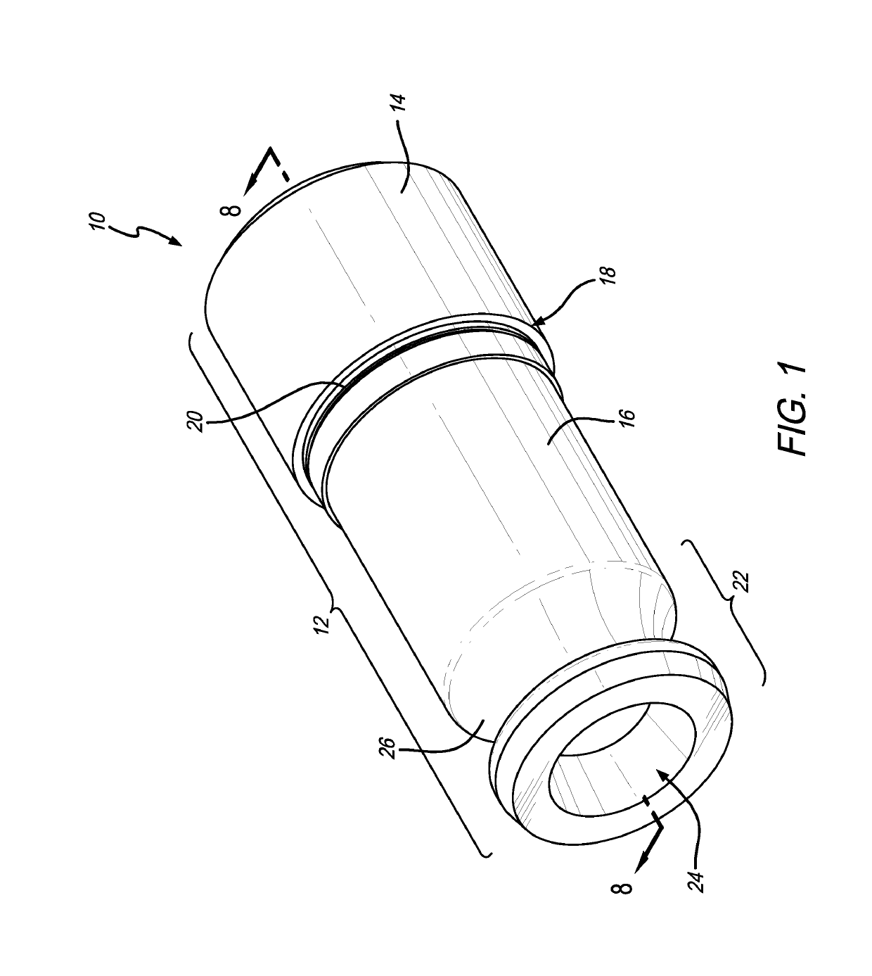
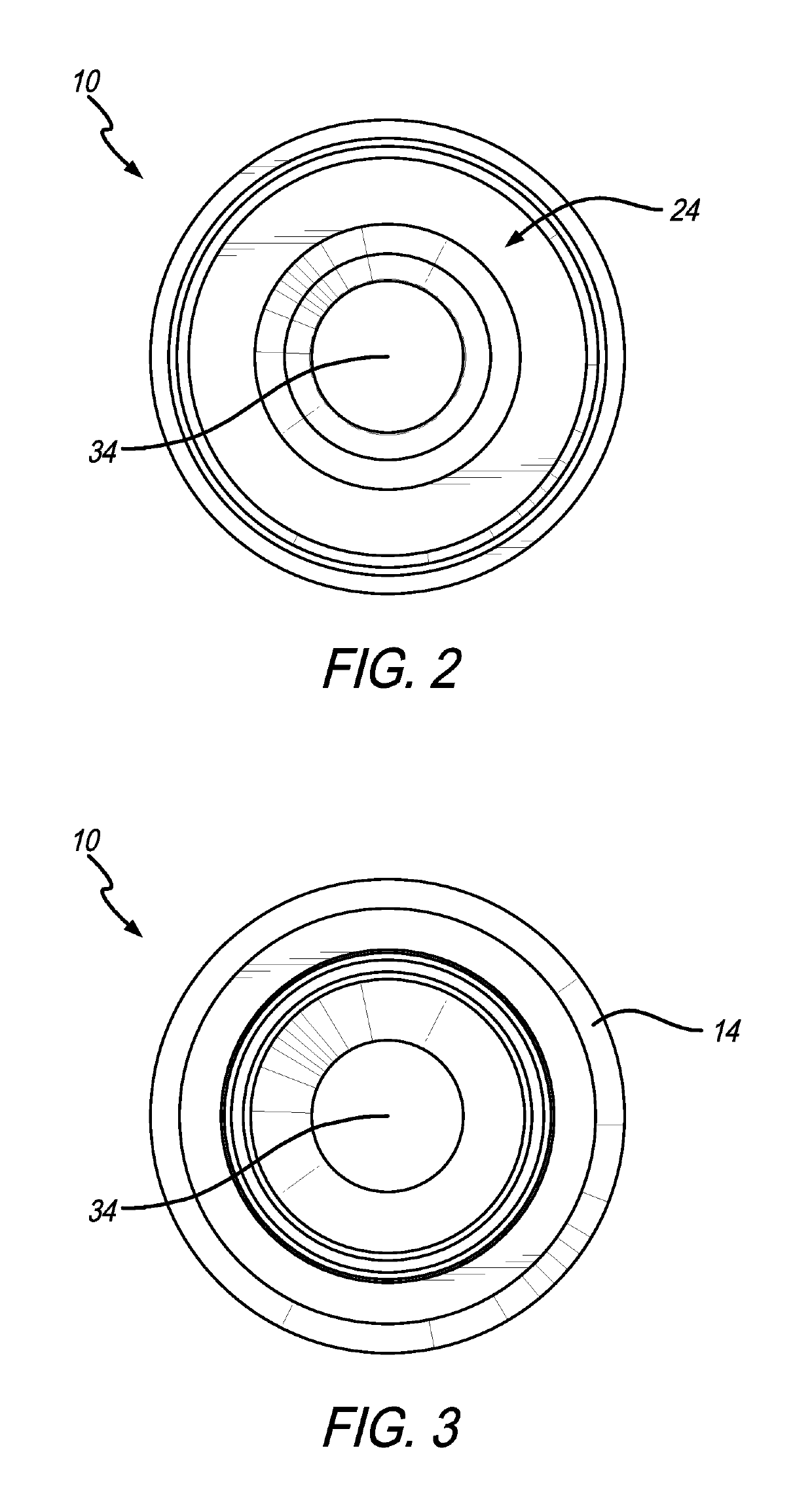
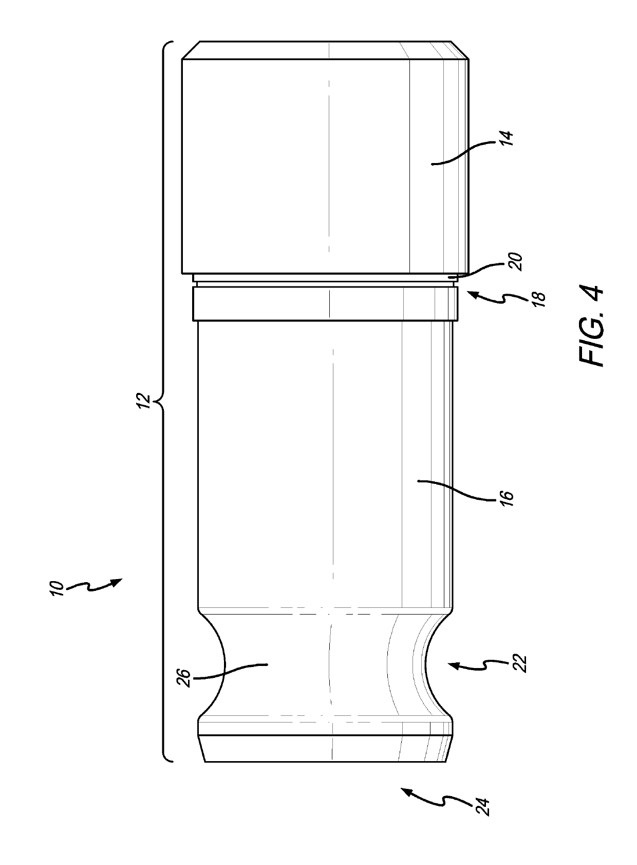
[0030]As shown in the exemplary drawings for purposes of illustration, one embodiment of an improved show head nozzle as disclosed herein is generally referred to in FIGS. 1-12 by reference numeral 10. Preferably, the shower head nozzle 10 includes integration of a quick-connection profile that permits attachment directly into the body of the shower head nozzle 10 to more quickly and accurately perform a weekly ANSI test on an emergency shower or the like.

[0031]More specifically with respect to FIGS. 1-8, one embodiment of the shower head nozzle 10 is shown having an elongated cylindrical body 12 with an upper end 14 formed next to a relatively smaller diameter intermediate section 16. In this respect, the transition area 18 between the upper end 14 and the intermediate section 16 may include a ledge or step 20 that allows the upper end 14 to be selectively engaged or otherwise be retained within the shower head (not shown). The intermediate section 16 then projects downwardly from ...


PUM

PropertyMeasurementUnit
diameteraaaaaaaaaa
diameteraaaaaaaaaa
outer diameteraaaaaaaaaa

Abstract

The shower head nozzle as disclosed herein includes a quick-connect coupling for selectively attaching the nozzle to a downwardly extending conduit or tube for directing tested water through a test unit and into a bucket or drain, wherein the test unit may include a flow meter for measuring real-time water flow rate and a temperature sensor for measuring real-time water temperature dispensed from the shower head, thereby reducing the testing time, more accurately determining flow-rate and water temperature, and decreasing the amount of waste water.

Description

CROSS-REFERENCE TO RELATED APPLICATION[0001]This application is based upon and claims priority to U.S. provisional patent application 62 / 255,339, entitled “Shower Head Nozzle,” filed Nov. 13, 2015.BACKGROUND OF THE INVENTION[0002]The present invention generally relates to a shower head nozzle for use with emergency showers and the like. More specifically, the present invention relates to a shower nozzle having an integrated quick-coupling for select drip-tight attachment to a drain system for use in more accurately testing the functionality (e.g., flow rate and water temperature) of an emergency shower or the like.[0003]The Occupational Safety and Health Administration (“OSHA”) requires that facilities provide, for immediate emergency use, equipment for quick drenching or flushing of the eyes and body within work areas where the eyes or body of any person may be exposed to injurious or corrosive materials. Such drenching or flushing devices known in the art may include an eyewash un...

Claims


Application Information

Patent Timeline
Patent Type & Authority Patents(United States)
IPC IPC(8): A47K3/28F16L37/18G01F15/18G01K13/02B05B12/00A61H35/02A61H35/00A61H33/00B05B15/654B05B1/18G01K1/14
CPCG01F15/185A61H35/00B05B1/18B05B1/185B05B12/002B05B12/008B05B15/654F16L37/18G01K1/14G01K13/02A47K3/286G01K2013/026A61H35/02A61H2033/0033A61H2201/5043A61H2201/5082G01K13/026
Inventor JOYER, MICHAELSMALL, DANIEL
Owner HAWS CORP
Why Eureka
Try Eureka