Power over ethernet devices

a technology of power over ethernet and ethernet devices, applied in the direction of data switching details, transmission, single ac network with different frequencies, etc., can solve the problems of melted wires, potential fires, limited power that can be transferred using poe, etc., to reduce power dissipation and cost saving

Active Publication Date: 2019-08-20
EXTREME LOW ENERGY
View PDF7 Cites 4 Cited by
  • Summary
  • Abstract
  • Description
  • Claims
  • Application Information

AI Technical Summary

Benefits of technology

[0025]The PoE cable will typically comprise more than two power wire pairs, for example, four power wire pairs. In some embodiments the internal power supply component may use two power wire pairs of the PoE cable and the external power supply component may use two other power wire pairs of the PoE cable that can utilise PoE mode A and mode B simultaneously. Instead of delivering all power to one high power device via a four-pair solution, the same four-pair configuration can be used to power two-pair power to a plurality of powered devices, e.g. two energy efficient devices using a total of <30 W of power. The balancing of the transmitted power along with reduced power dissipation and energy can translate into further cost savings
[0047]Such image processing devices can be placed in remote locations without AC Power and only require a network cable to operate. This can make the devices more lightweight, cheaper to manufacture, less parts to manufacture (so better for the environment / recycling), reduced power loss, and improved flexibility in terms of positioning, etc.

Problems solved by technology

Also, the amount of power that can be transferred using PoE is limited (typically around 13-25 W).
However, the use of a standard Ethernet-cabling infrastructure for a single port delivering greater than 100 W is not safe under the current US National Electric Code standard and increasing loads could result in overheating causing melted wires and potential fires.

Method used


Image

  • Power over ethernet devices
  • Power over ethernet devices
  • Power over ethernet devices

Examples


Embodiment Construction

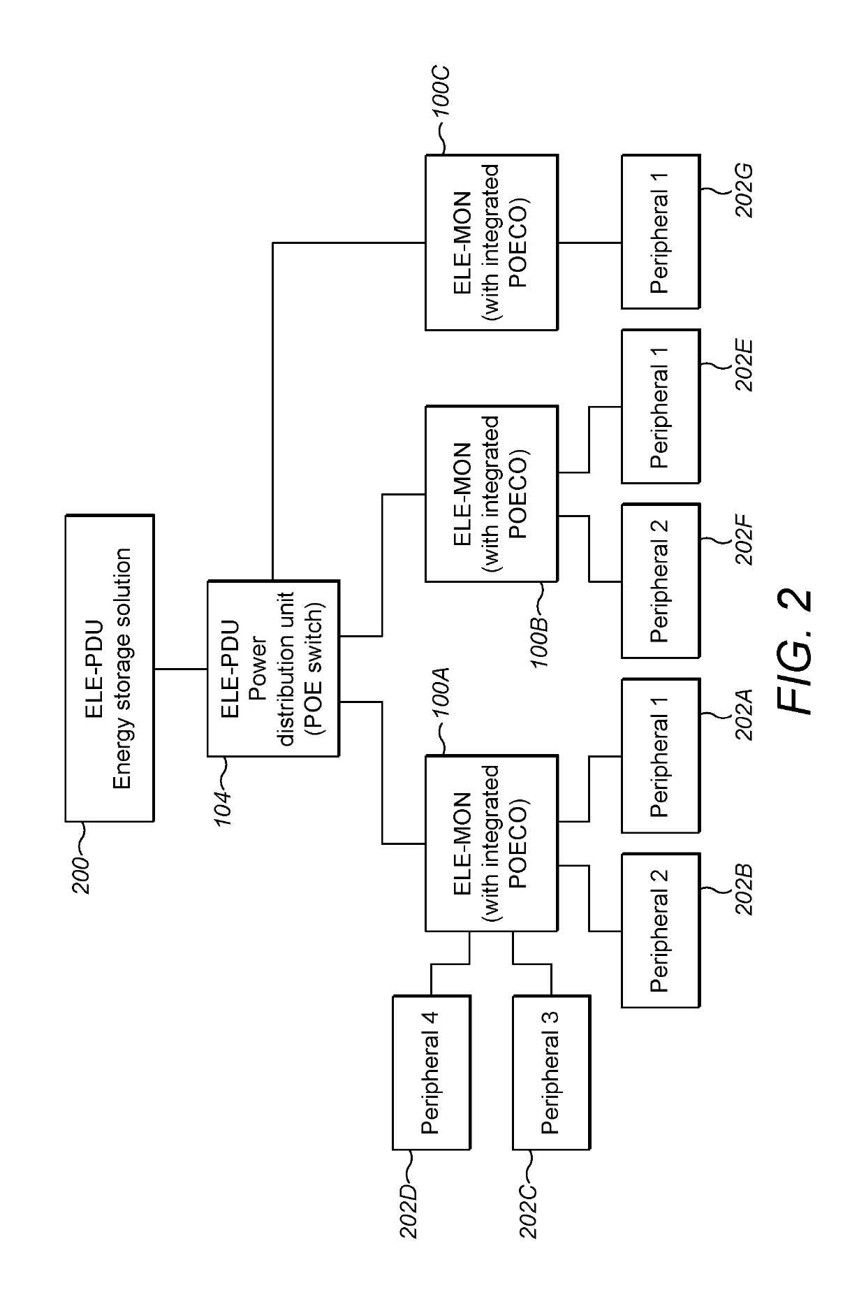
[0056]Example embodiments of the present invention will be described in detail with reference to the accompanying drawings. Referring first to FIG. 1 there is shown an example PoE connector device 100 that is connected, via a network cable 102, to a power distribution unit (PDU) 104. The cable can comprise any suitable Ethernet cable cat5e and above, such as 24 AWG (American Wire Gauge).

[0057]The PDU 104 receives power, typically from a DC power supply such as a Power storage unit / batteries (not shown), which is distributed to power / data ports via four internal transformers 106A-106D. The secondary coil of each of these transformers is fitted with a pair of pins, which are conventionally numbered 1, 2; 4, 5; 7, 8; 3, 6.

[0058]The connector device 100 also includes a set of four internal transformers 108A-108D. Each of these transformers is also fitted with a pair of pins, conventionally numbered 1, 2; 4, 5; 7, 8; 3, 6.

[0059]The network cable 102 comprises four twisted pairs 110A-110D...


PUM


Abstract

A Power over Ethernet, PoE, connector device (100) comprises a first connector (112) for, in use, connecting a first set comprising at least one power wire pair (110A, 110D) of a PoE cable (102) to a first powered device (116). The PoE connector device further comprises a second connector (114) for, in use, connecting a second set comprising at least one other power wire pair (110B, 110C) of the PoE cable to at least one further powered device (118). Embodiments also provide a display device and a computing system.

Description

FIELD OF THE INVENTION[0001]The present invention relates to Power over Ethernet (PoE) and to related methods and devices.BACKGROUND TO THE INVENTION[0002]Power over Ethernet (PoE) is a known technology that allows network cables to carry electrical power. Thus, PoE-enabled devices can receive power as well as data through the twisted pairs of an Ethernet cable. PoE can provide many advantages for installations, including reducing time and expense of installing electrical power cables. PoE-enabled devices do not require mains AC electrical outlets to operate and PoE systems can also protect equipment from overload.[0003]The 802.3 PoE standard defines two types of PoE implementation:[0004]Mode A—power is sent together with the data on twisted pairs 1 / 2 & 3 / 6 of the Ethernet cable[0005]Mode B—data is sent on pairs 1 / 2 & 3 / 6, and power is sent on pairs 4 / 5 and 7 / 8 of the Ethernet cable as pairs 4 / 5 and 7 / 8 are unused in Fast Ethernet networks. In the case of Gigabit and 10G Ethernet al...

Claims


Application Information

Patent Timeline
Patent Type & Authority Patents(United States)
IPC IPC(8): H02J3/02H04L12/40H04L12/10
CPCH04L12/10H04L12/40045H02J3/02
Inventor BUCHANAN, MARK
Owner EXTREME LOW ENERGY
Why Eureka
Try Eureka