Loading dock rail shelter

a dock rail and rail shelter technology, applied in the direction of loading/unloading, aircraft components, ground installations, etc., can solve the problems of not holding the entire canopy against the building wall, maintaining the required clearance,

Active Publication Date: 2019-08-27
NORDOCK
View PDF10 Cites 3 Cited by
  • Summary
  • Abstract
  • Description
  • Claims
  • Application Information

AI Technical Summary

Problems solved by technology

Conventional rail shelters suffer from a variety of problems.
One problem is maintaining a required amount of clearance between the deflated shelter and the railcars passing along the railroad tracks.
These cords deteriorate, fatigue and break over time, so that they do not effectively hold the entire canopy against the building wall.
High winds or gusts of wind can catch a portion of the deflated canopy and blow it toward and into the structure-free zone by the tracks, where it can be struck or snagged by or interfere with a passing train.
Another problem with conventional loading dock rail shelters is that the sides and bottom of the canopy drag along the ground when inflating and deflating.
This problem is of particular concern for four-sided canopies with a bottom portion.
The ground along the tracks includes stones, sticks and debris such as broken bottles, crushed cans, boards and nails, etc., that are rough, sharp and jagged, and which can damage the canopy.
While bungee cords may reduce the amount of dragging in some situations, they do not eliminate this problem, particularly for four-sided canopies and when the tracks are located further from the building and the canopy must extend a greater distance.
A further problem with conventional loading dock rail shelters is that they do not properly stabilize the canopy when inflated.
High winds and gusts of wind can easily push the extended canopy back and forth over rusted, blunt,

Method used


Image

  • Loading dock rail shelter
  • Loading dock rail shelter
  • Loading dock rail shelter

Examples


Embodiment Construction

[0035]While this invention is susceptible to embodiment in many different forms, the drawings show and the specification describes in detail a preferred embodiment of the invention. It should be understood that the drawings and specification are to be considered an exemplification of the principles of the invention. They are not intended to limit the broad aspects of the invention to the embodiment illustrated.

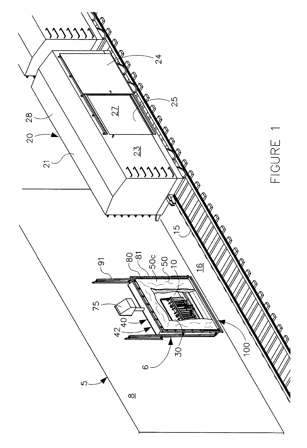
[0036]Modern commercial buildings 5 for manufacturing, warehousing, distributing and selling goods are equipped with loading docks or bays 6 to efficiently move goods, supplies, furniture, equipment and other forms of cargo in and out of the building. The loading docks 6 have a generally flat, horizontal, elevated floor surface 7 relative to its generally vertical and planar exterior walls 8 to define the interior 9 of the building 5 as shown in FIG. 1. The loading bay 6 has an elevated doorway or opening 10. A door such as an overhead door (not shown) is used to selectively o...


PUM


Abstract

The present invention is a loading dock rail shelter with an inflatable canopy and a dual stabilizing and passive retraction support assembly. The canopy has an outer end that moves between inflated and retracted positions. The support assembly includes a rigid frame secured around the perimeter of the canopy, and a pivoting support mechanism that allows the frame to ride with the canopy while supporting and guiding the canopy. The shelter has a lower panel assembly that close the bottom of the canopy. The lower panel has lateral support rods and a front panel support assembly secured to the frame. The support assembly supports the canopy and its lower panel so they do not drag along the ground. The rigid frame stabilizes and guides the inflating canopy to seal around a railcar doorway. The support assembly and frame swing back to passively retract and hold the canopy against the building.

Description

TECHNICAL FIELD OF THE INVENTION[0001]This invention relates to a loading dock rail shelter with an inflating canopy and dual stabilizing and passive retraction support mechanism that keeps the canopy off the ground, guides and stabilizes the canopy to seal around a railcar doorway, and passively retracts to hold the canopy against the loading dock wall and protect it from damage by wind and weather.BACKGROUND OF THE INVENTION[0002]Loading dock rail shelters form a temporary enclosure between a railroad car and the loading bay of a building. Rail shelters are typically used in conjunction with a dock leveler that forms a bridge between the dock and railcar floors. The shelters prevent rain, snow and ice from accumulating on the floors of the loading bay, railcar, dock leveler and the cargo, and provide a safer environment for loading and unloading operations. Rail shelters can have three or four sides. Three-sided shelters have a top and two side portions that extend over and around...

Claims


Application Information

Patent Timeline
IPC IPC(8): B65G9/00B65G69/00B65G69/28B64F1/305
CPCB64F1/305B65G69/008B65G69/2811
Inventor GLEASON, DENISBARRETT, ANDREW
Owner NORDOCK
Why Eureka
Try Eureka