Pipe lifter

a technology of pipe lifter and pipe, which is applied in the direction of pipe laying and repair, load-engaging elements, pipes/joints/fittings, etc., can solve the problems of inefficiency and time-consuming of the apparatus that can only move one pipe at a tim

Active Publication Date: 2019-08-27
PRECISION PIPE ELEVATORER PTY LTD
View PDF20 Cites 0 Cited by
  • Summary
  • Abstract
  • Description
  • Claims
  • Application Information

AI Technical Summary

Benefits of technology

[0014]Preferably the lengthening means includes a hydraulic or pneumatic ram that can extend and shorten the length of the elongate member.

Problems solved by technology

The disadvantage to this arrangement is that multiple pipes need to be moved in some situations and the use of lifting apparatus that can only move one pipe at a time is inefficient and time consuming.

Method used


Image

  • Pipe lifter
  • Pipe lifter
  • Pipe lifter

Examples


Embodiment Construction

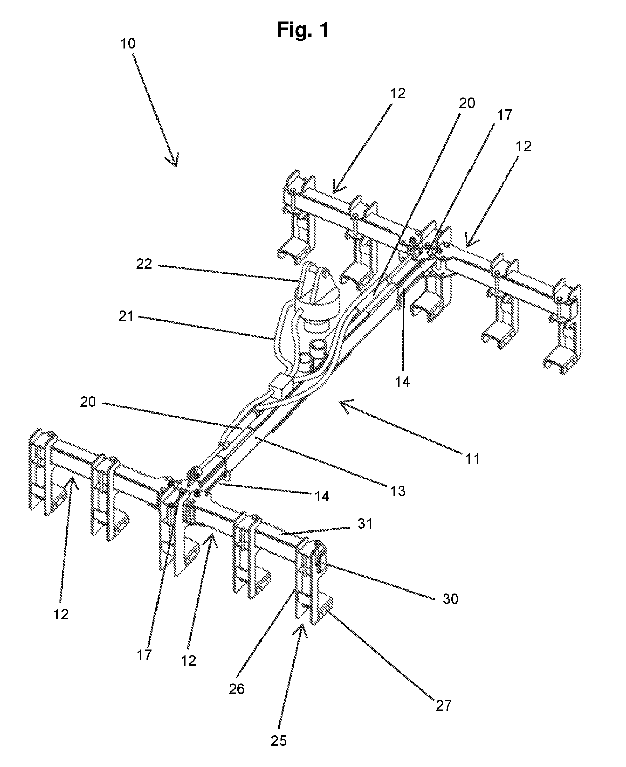
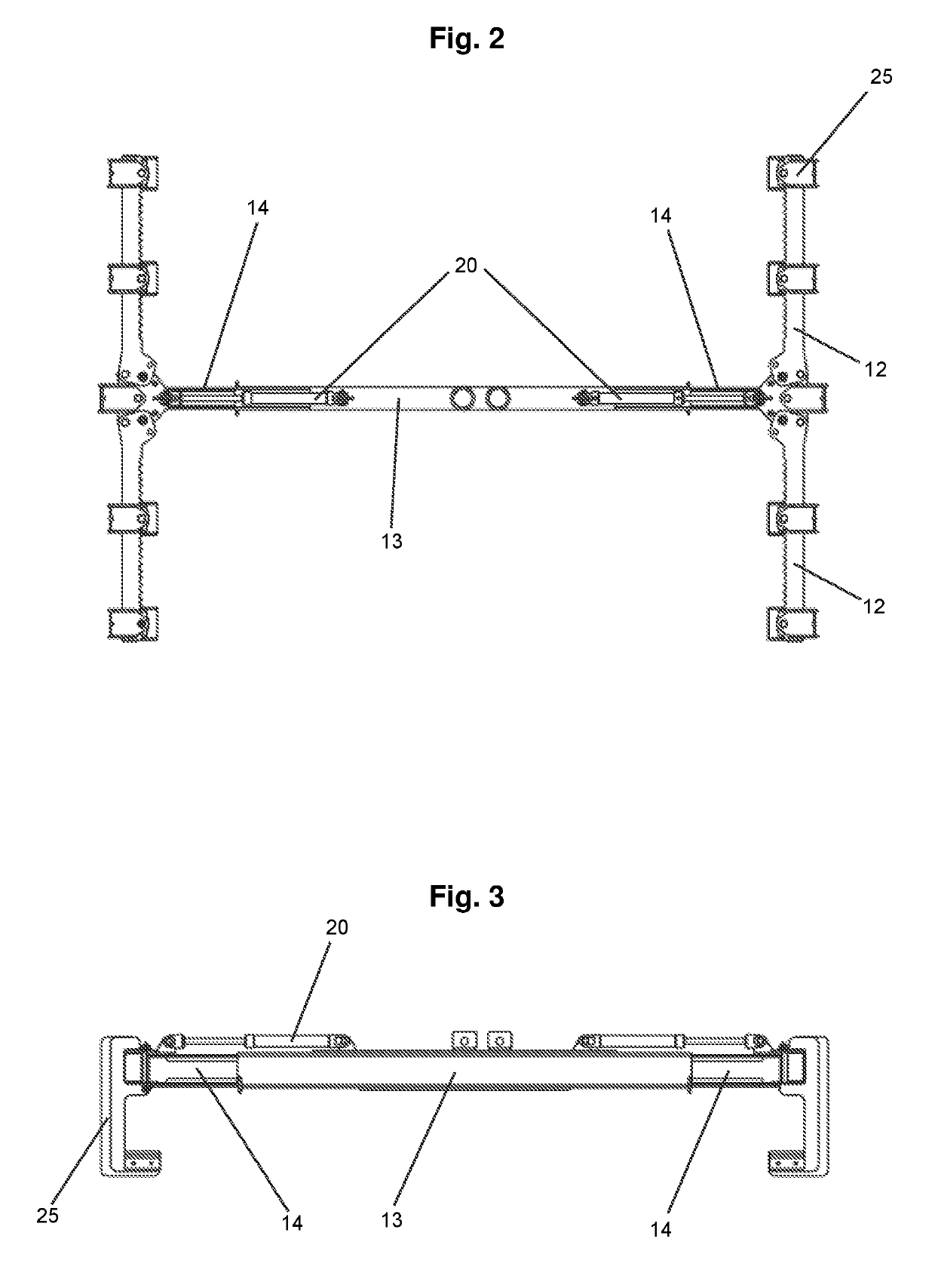
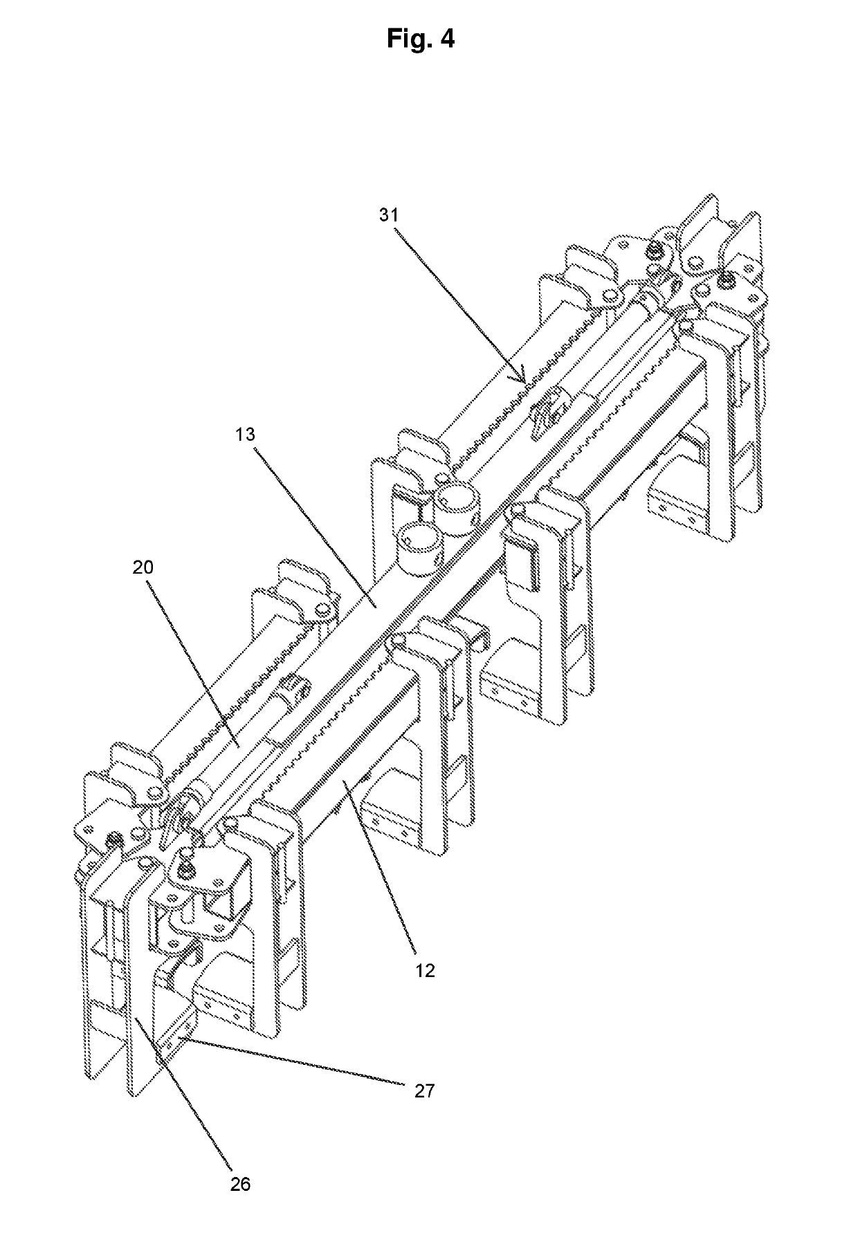
[0063]With reference to the FIGS. 1 to 9, there is shown a preferred embodiment of the pipe lifter 10. The pipe lifter 10 included a slideable elongate member 11 with laterally extending arms 12 pivotally attached to each end of the elongate member 11. The elongate member 11 comprises three parts where there is an outer sleeve 13 and two inner sleeves 14. The inner sleeves 14 are slideably retained within the outer sleeve 13. Each free end of the inner sleeve 14 is attached to the pivotally attached lateral arms 12. The lateral arms 12 are attached to a connecting plate 17 which is fixed to the free end of the inner sleeves 14. A hydraulic ram 20 is connected to the connecting plate 17 and the outer sleeve 13. When the hydraulic ram 20 is actuated it pushes the connecting plate 17 away from the outer sleeve 13 or draws the connecting plate 17 towards the outer sleeve 13. As there are two hydraulic rams 20 operationally associated with the inner sleeves 14 at each end of the elongate...


PUM


Abstract

A pipe lifter for carrying one or more pipes including a slidably extendable elongate member and two sets of two laterally extending arms on each side of the elongate member. Each set of the two laterally extending arms are opposed to each other. Each of the laterally extending arms is pivotally fixed to the elongate member and moveable between a folded position where the arm is adjacent and parallel with the elongate member and an operational position where the arm extends laterally substantially at ninety degrees with respect to the elongate member. There are two or more L-shaped support members attachable to the laterally extending arms. There is also a hydraulic or pneumatic ram operationally configured to extend and shorten the length of the elongate member. In use, the L-shaped support members attached to the opposing laterally extending arms are positioned to be substantially opposing each other and the length of the elongate member is adjusted so that the outwardly extending section of the L-shaped support pipe is locatable within each open end of the pipe to secure the pipe to the pipe lifter.

Description

CROSS REFERENCE TO RELATED APPLICATION[0001]This application is a national phase of International Patent Application No. PCT / AU2017 / 050213 filed Mar. 9, 2017, and which claims the priority filing benefit of Australian Patent Application No. 2016900894 filed Mar. 10, 2016, both of which are incorporated herein by reference in their entirety.FIELD OF INVENTION[0002]The present invention relates to apparatus for the lifting of pipes, tubes, casings and similar items. The present invention has particular but not exclusive application for use in lifting multiple concrete pipes. Reference in the specification to concrete pipes is by way of example only and the invention is not limited to concrete pipes.BACKGROUND OF THE INVENTION[0003]Concrete pipes are lifted to and from trucks and into an in-use position by the use of hooks, clamps and harnesses. The hooks, clamps and harnesses are attached to a crane, forklift or excavator. Harnesses are often one or more chain slings that are position...

Claims


Application Information

Patent Timeline
Patent Type & Authority Patents(United States)
IPC IPC(8): B66C1/62B66C1/68F16L1/032
CPCB66C1/68F16L1/032B66C1/62
Inventor TAYLOR, CHRISTOPHER KENT
Owner PRECISION PIPE ELEVATORER PTY LTD
Why Eureka
Try Eureka