Method and system for low temperature detection of semi volatile organic compounds

a low temperature detection and organic compound technology, applied in the field of methods and systems for low temperature detection of semi volatile organic compounds, can solve the problems of complicated sample analysis process, additional challenges, and problems, and achieve the effects of reducing detection limits, reducing gold reflectivity, and reducing costs

Active Publication Date: 2019-09-03
MLS ACQ INC
View PDF4 Cites 5 Cited by
  • Summary
  • Abstract
  • Description
  • Claims
  • Application Information

AI Technical Summary

Benefits of technology

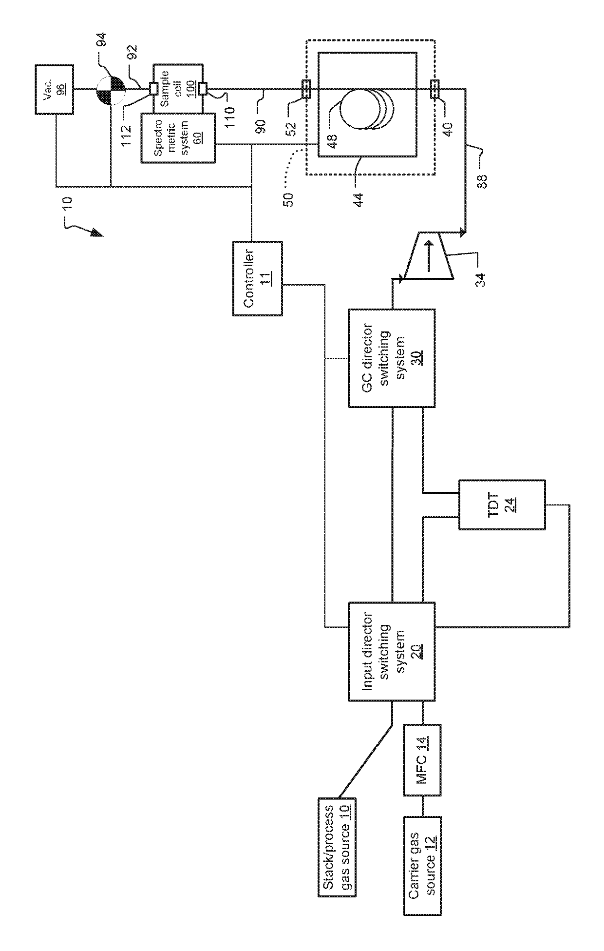
[0014]In the analysis system and method described herein, condensation in the sample cell is prevented or minimized by expanding the gas from the small volume it occupies before emerging from a GC column to a larger volume presented by an appropriately configured sample cell. The expansion effects a drop in the vapor pressure of the analyte. As a consequence, SVOC analytes can remain in their vapor phase even when the gas cell is held at a temperature below their normal boiling point (defined as the temperature at which a liquid boils at 1 atmosphere of pressure).
[0016]By practicing approaches described herein, the sample cell can be operated at lower temperatures than otherwise needed to maintain SVOCs in the vapor (gas) phase. This is particularly advantageous in cells that utilize gold-coated optics, since it is known that as the temperature rises, the reflectivity of gold decreases. With a multiple path cell design, a modified White cell, for example, that includes gold reflecting optics, a lower cell temperature can result in more light passing through the cell and, potentially, to lower detection limits.
[0017]Also, since IR gases have absorption spectra that depend on temperature, it is advantageous to choose a single temperature at which to operate the detector (sample cell) so that the collected sample spectra are only measured at one temperature and will match the quantified spectral library without having to vary the gas cell temperature with time or for a specific list of compounds.
[0018]Techniques described herein provide flexibility in how the sample cell is operated. While in many cases a preferred temperature for the gas cell may be 191° C., the cell can be heated as needed, to a temperature of about 200 or 250° C., for example. Spectral calibrations could be collected at the higher temperature, as needed.
[0019]Some of the approaches described herein are associated with lower costs and / or simplified procedures. In cases in which thermal desorption tubes (TDTs) are employed, these devices can be packed with inexpensive materials. In addition to realizing costs benefits, a packing that is nothing more than glass wool, for example, will not trap VOCs or water. In the absence of VOCs and / or water, much larger samples containing SVOCs can be collected on the TDT.
[0020]It is also possible to bypass solvent extraction steps traditionally used to prepare samples containing SVOCs, thus simplifying the process, reducing the cost of materials as well as waste disposal requirements.

Problems solved by technology

Additional challenges can be encountered when this gas contains semi volatile organic compounds, also known as SVOCs, since this subgroup of volatile organic compounds (VOCs) is typically characterized by higher molecular weights and higher boiling point temperatures.
Having to heat the FTIR sample cell to temperatures sufficient to maintain SVOCs above their normal boiling point may complicate the sample analysis process.
Problems also can be encountered with sample cells configured for multiple path absorption and employing gold-based optics.
Since it is known that the reflectivity of gold decreases with increased temperatures, light losses associated with the higher temperatures needed when handling SVOCs can have a negative impact on detection limits.

Method used


Image

  • Method and system for low temperature detection of semi volatile organic compounds

Examples


Embodiment Construction

[0024]The invention now will be described more fully hereinafter with reference to the accompanying drawings, in which illustrative embodiments of the invention are shown. This invention may, however, be embodied in many different forms and should not be construed as limited to the embodiments set forth herein; rather, these embodiments are provided so that this disclosure will be thorough and complete, and will fully convey the scope of the invention to those skilled in the art.

[0025]As used herein, the term “and / or” includes any and all combinations of one or more of the associated listed items. Further, the singular forms and the articles “a”, “an” and “the” are intended to include the plural forms as well, unless expressly stated otherwise. It will be further understood that the terms: includes, comprises, including and / or comprising, when used in this specification, specify the presence of stated features, integers, steps, operations, elements, and / or components, but do not pre...


PUM

PropertyMeasurementUnit
temperatureaaaaaaaaaa
pressureaaaaaaaaaa
temperatureaaaaaaaaaa

Abstract

A sample analysis method includes directing a sample that contains one or more SVOC components to a GC column to temporally separate components present in the sample. Output gas from the GC column is expanded into a sample cell. The sample cell is held at a temperature and pressure that are lower than the temperature and pressure at an outlet of the GC column. The volume of the sample cell is sufficiently large for maintaining the one or more SVOC components in a gaseous phase. Infrared spectra of the components in the sample cell are obtained using a Fourier transform infrared spectrometry system.

Description

RELATED APPLICATIONS[0001]This application claims the benefit under 35 USC 119(e) of U.S. Provisional Application No. 62 / 438,304, filed on Dec. 22, 2016, which is incorporated herein by reference in its entirety.BACKGROUND OF THE INVENTION[0002]Gas chromatography (GC) is an analytical method that measures the content of various components in a sample. The method for separating chemical substances relies on differences in partitioning behavior between a flowing mobile phase (gas phase) and a stationary phase supported in a column to separate the components in a mixture. As the gas flow passes through the column, the sample components move at velocities that are influenced by the degree of interaction of each component with the stationary phase in the column. Consequently, the different components separate in time as the components elute from the column.[0003]While GC is widely used to resolve a mixture into its various components according to retention profiles of the different molec...

Claims


Application Information

Patent Timeline
Patent Type & Authority Patents(United States)
IPC IPC(8): G01N30/02G01N30/74G01N21/05G01N1/22G01N30/14G01N1/42G01N30/30G01N30/12G01N21/35
CPCG01N30/74G01N21/05G01N1/22G01N30/14G01N2021/3595G01N1/42G01N2030/128G01N2030/743G01N2030/025G01N2030/143G01N2030/3038
Inventor SPARTZ, MARTIN L.DELIA, ALICE ELIZABETHBEHNKE, PETER PAULPHILLIPS, CHARLES MARK
Owner MLS ACQ INC
Why Eureka
Try Eureka