Ribbon array microphone

a ribbon microphone and array technology, applied in the field of audio processing, can solve the problems of limiting the use of ribbon microphones, low output levels, and very delicate ribbon microphones, and achieve the effect of reducing some of the drawbacks

Active Publication Date: 2019-09-03
ABEL JONATHAN S
View PDF3 Cites 6 Cited by
  • Summary
  • Abstract
  • Description
  • Claims
  • Application Information

AI Technical Summary

Benefits of technology

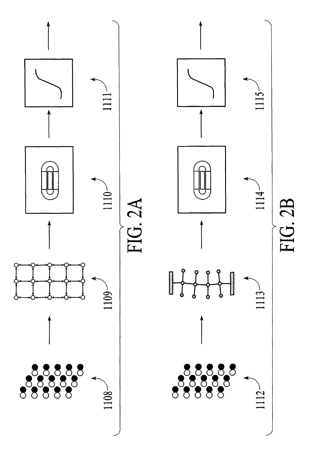
[0012]According to some aspects, embodiments of the invention take an array of microphone elements, either very small microphones that are placed on either side of a printed circuit board or some other device to understand the sound pressure differences from front to back and use those sound pressure differences to emulate the motion of a ribbon if a ribbon were co-located with the array of microphones. So the microphone array detects differential pressure, either by a set of elements that that have figure of eight polar patterns, or by having separate elements front and back. Embodiments of the invention detect differential pressure, either along an area, for example a two-dimensional grid or a single line array of differential pressure elements, or two rows of elements that provide an understanding of the dynamics of the ribbon microphone in terms of both a transverse displacement and a tortional displacement. An aspect of the invention is to take the microphones' signals, which indicate differential pressure front to back, and use those differential pressu

Problems solved by technology

So, sound impinging on this strip will cause it to vibrate.
So, these ribbon microphones are very delicate, mechanically and acoustically.
If one were to blow on a ribbon microphone it would break.
So, this sensitivity to acoustics, as well as the mechanical sensitivity inherent in these microphones, does limit their use.
So, they have a few drawbacks in terms of their mechanical and acoustic robustness, so they also have low output levels and these things limit their usage.
The issues with conventional ribbon microphones include that they are very delicate, mechanically and acoustically.
If one were to blow onto the ribbon it would

Method used


Image

  • Ribbon array microphone
  • Ribbon array microphone
  • Ribbon array microphone

Examples


Embodiment Construction

[0024]The present invention will now be described in detail with reference to the drawings, which are provided as illustrative examples of the invention so as to enable those skilled in the art to practice the invention. Notably, the figures and examples below are not meant to limit the scope of the present invention to a single embodiment, but other embodiments are possible by way of interchange of some or all of the described or illustrated elements. Moreover, where certain elements of the present invention can be partially or fully implemented using known components, only those portions of such known components that are necessary for an understanding of the present invention will be described, and detailed descriptions of other portions of such known components will be omitted so as not to obscure the invention. Embodiments described as being implemented in software should not be limited thereto, but can include embodiments implemented in hardware, or combinations of software and...


PUM


Abstract

The invention includes a basic approach to simulate the workings of a ribbon microphone based on measurements at an array of more robust small pressure microphones. Embodiments of the invention take an array of microphone elements, either very small microphones that are placed on either side of a printed circuit board or some other device to understand the sound pressure differences from front to back and use those sound pressure differences to emulate the motion of a ribbon if a ribbon were co-located with the array of microphones. The microphone array detects differential pressure, either by a set of elements that that have figure of eight polar patterns, or by having separate elements front and back.

Description

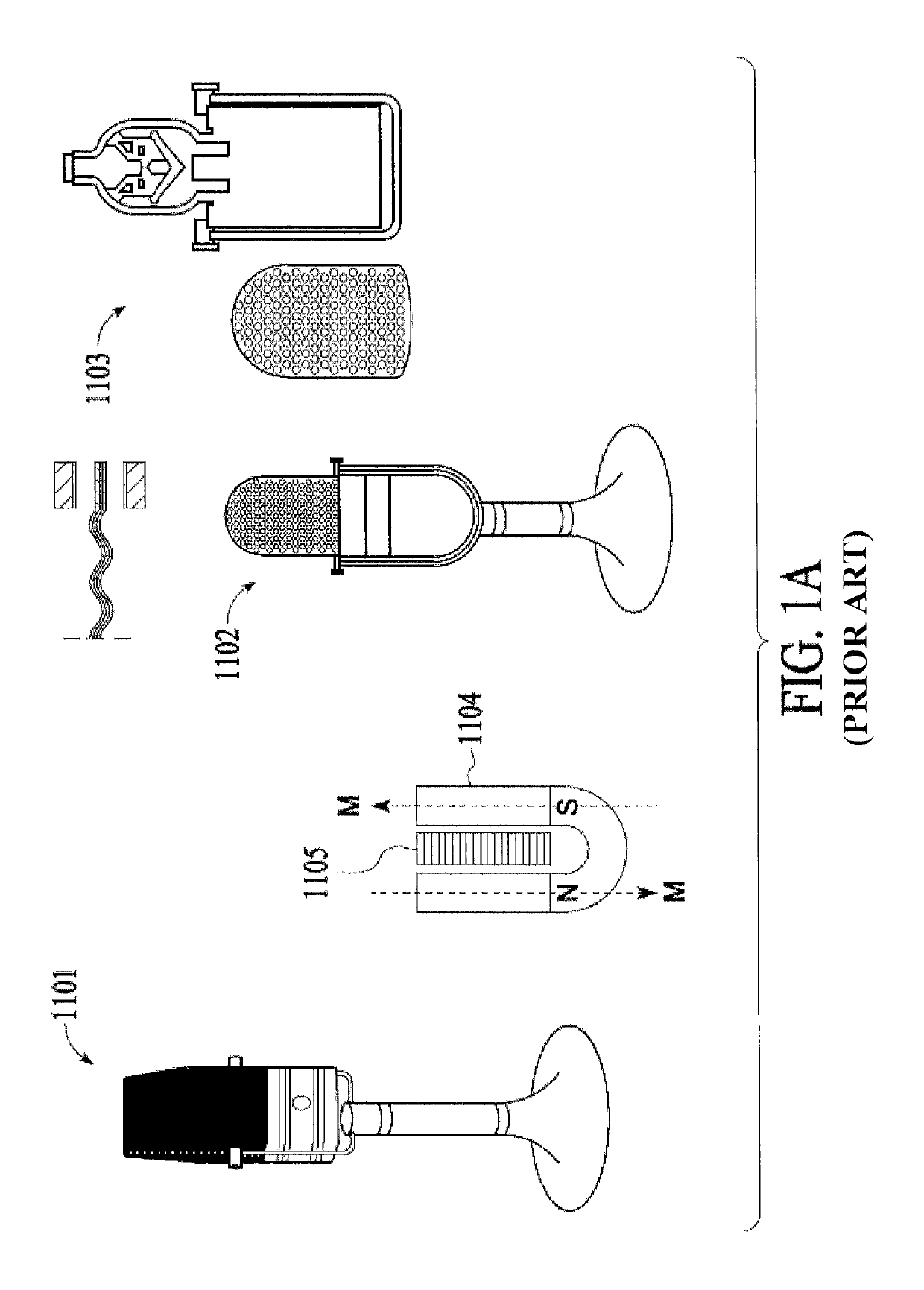
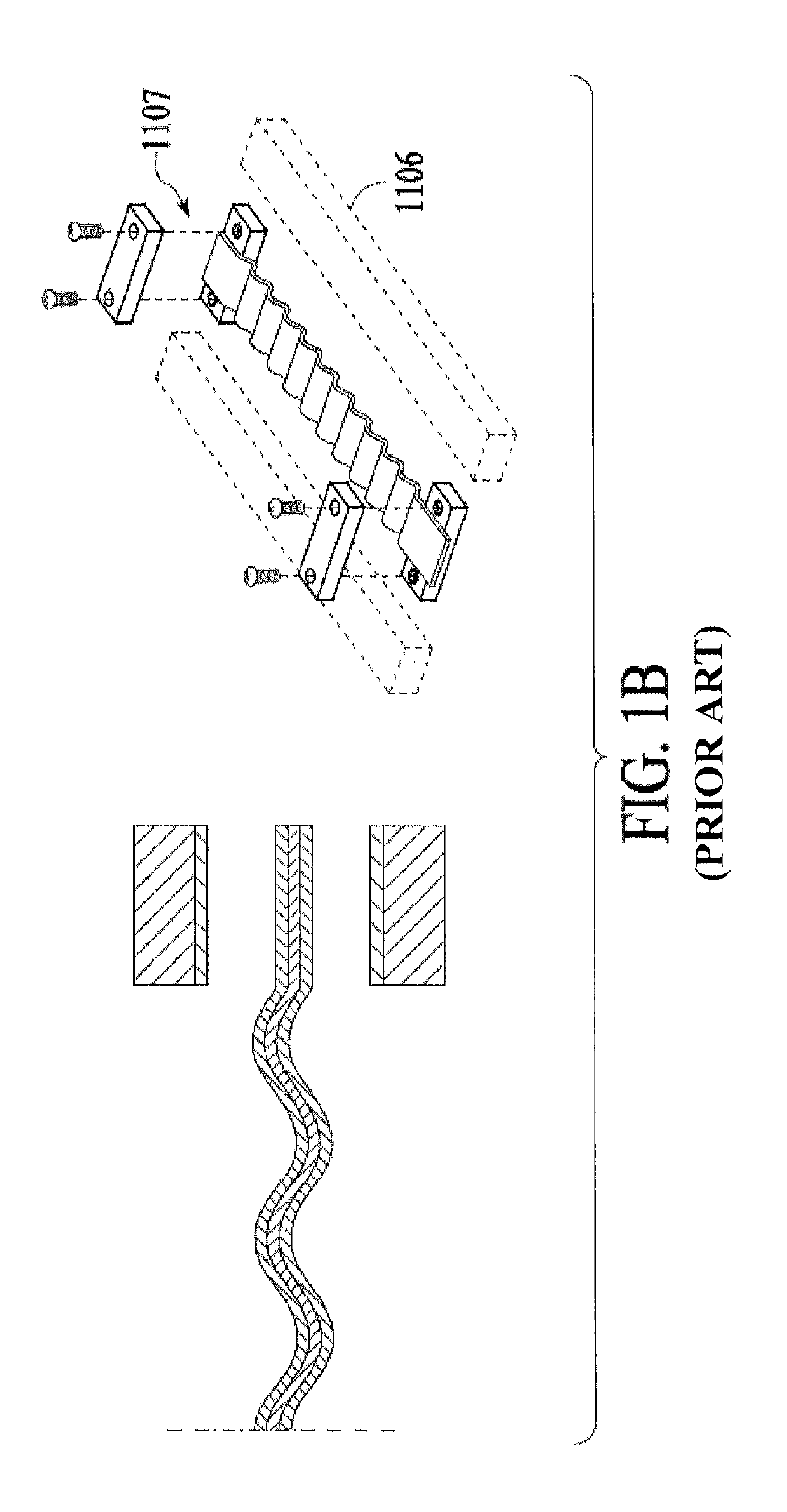
CROSS-REFERENCE TO RELATED APPLICATIONS[0001]The present application claims priority to U.S. Provisional Application No. 61 / 379,342, filed Sep. 1, 2010, the contents of which are incorporated by reference herein in their entirety.FIELD OF THE INVENTION[0002]In general, the invention is related to audio processing, and in particular to an emulation of a ribbon microphone.BACKGROUND OF THE INVENTION[0003]Ribbon microphones are known for their sort of warm natural sonics. They have really desirable characteristics especially for things like vocals. And, what they do, they consist of a ribbon which is a very, very thin corrugated sheet of aluminum that is suspended in a magnetic field. Incoming sound waves cause the ribbon to vibrate, moving conductor in a magnetic field will generate a voltage across the conductor and be an indicator of the sound field. So there are a number of manufacturers, probably the most famous initial group of microphones is made by RCA.[0004]FIGS. 1A and 1B ill...

Claims


Application Information

Patent Timeline
IPC IPC(8): H04R19/04H04R29/00
CPCH04R19/04H04R29/005H04R3/005H04R9/048H04R2201/401
Inventor ABEL, JONATHAN S.
Owner ABEL JONATHAN S
Why Eureka
Try Eureka