

Multi-stage vacuum ejector
Patent Information
- Authority / Receiving Office
- US · United States
- Patent Type
- Patents(United States)
- Current Assignee / Owner
- ONISHIVACUUM AB
- Publication Date
- 2019-09-10
Smart Images
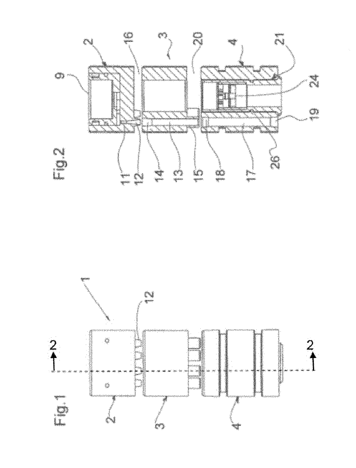
Figure 1 
Figure 2 
Figure 3
Abstract
Description
BACKGROUND AND SUMMARY
[0001] The present invention relates to a vacuum ejector for producing vacuums in industrial processes. More specifically, the invention relates to a multi-stage vacuum ejector in which the ejector stages are arranged in series and / or in parallel.
[0002] A multi-stage ejector having a plurality of ejector stages arranged in series and / or in parallel has long been known.
[0003] Typical of a multi-stage ejector is that it comprises an ejector housing, comprising two or more ejector stages, also termed ejector units, axially arranged one after the other in series. In each of the ejector units there is arranged a compressed air duct comprising an ejector nozzle for producing the vacuum flow of the ejector and a vacuum duct for said vacuum flow. The ejector units are separated from one another via transverse partition walls disposed in the ejector housing.
[0004] Compressed air is fed to the multi-stage ejector via a hose coupling or pipe coupling disposed in the first eje...