
Long-range optical tag

a long-range, optical tag technology, applied in the direction of optical elements, instruments, using reradiation, etc., can solve the problems of limiting the speed, limiting the alignment range, and limiting the accuracy so as to facilitate the alignment of the optical tag, maximize the light received, and large aperture

Active Publication Date: 2019-09-10
CUBIC CORPORATION
View PDF9 Cites 0 Cited by
  • Summary
  • Abstract
  • Description
  • Claims
  • Application Information

AI Technical Summary

Benefits of technology

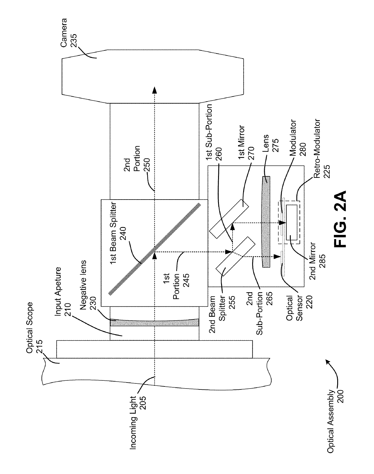
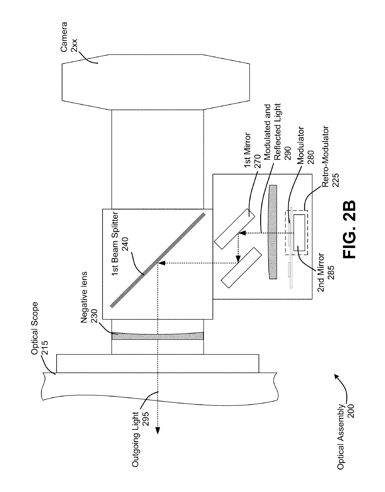
The patent describes an optical tag that can be detected simultaneously using a beam splitter and retro-modulated using a camera. This allows for better alignment with a laser interrogator. The optical tag can also use a large aperture to maximize light reception and minimize diffraction. A beam splitter can be used to balance the light directed towards the optical sensor and the retro-modulator, resulting in optimal performance. Overall, this technology improves the range and accuracy of optical tags.

Problems solved by technology

Traditional optical tags, however, suffer various trade-offs.
In particular, trade-offs exist between optical aperture, field of view (FOV) and modulator size, the latter of which limits the speed.
Problematically, however, the setup is impractical in many scenarios.

Method used


Image

  • Long-range optical tag
  • Long-range optical tag
  • Long-range optical tag

Examples


Embodiment Construction

[0013]The ensuing description provides preferred exemplary embodiment(s) only, and is not intended to limit the scope, applicability or configuration of the disclosure. Rather, the ensuing description of the preferred exemplary embodiment(s) will provide those skilled in the art with an enabling description for implementing a preferred exemplary embodiment. It is understood that various changes may be made in the function and arrangement of elements without departing from the spirit and scope as set forth in the appended claims.

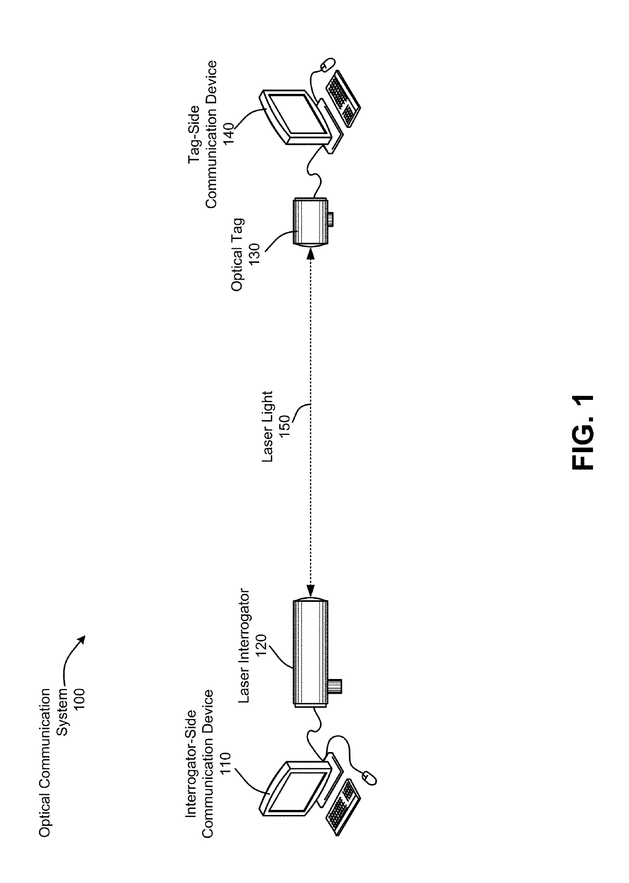
[0014]Optical tags provide unique means to transfer free space optical data in two directions by modulating and reflecting laser light emitted by a remote laser interrogator. This type of optical communication can have various advantages over radio frequency (RF), providing directional communication often with higher data rates than RF communication, and less susceptibility to jamming or other interference. It can also provide other advantages, such as reduce...


PUM


Abstract

Embodiments disclosed herein address these and other issues by providing for an optical tag that uses an optical assembly with beam splitters to allow for simultaneous detection and retro-modulation, as well as the use of a camera to facilitate alignment of the optical tag with a laser interrogator. Additional components may be used to allow for a large aperture to be used, to help maximize light received by the optical tag and minimize diffraction of retro-modulated light, which can significantly increase distances at which the optical tag can operate. Moreover, a beam splitter may further be used to balance the light directed toward an optical sensor and a retro-modulator, to help achieve optimal results.

Description

CROSS-REFERENCES TO RELATED APPLICATIONS[0001]This application claims the benefit of U.S. Provisional Patent Application No. 62 / 662,476, filed Apr. 25, 2018, entitled “Large Aperture, Long-Range Optical Tag System Embodiment,” which is assigned to the assignee hereof and incorporated by reference herein in its entirety.BACKGROUND[0002]Optical retro-modulators provide a unique means to transfer free space optical data without the need to generate and broadcast laser light, thereby saving much size, weight, and power at the retro-modulation and of an optical communication link between the optical retro-modulator and laser interrogator. Additionally, optical retro-modulators can be included in an optical “tag” with an optical receiver (which can detect and decode data received by modulated light from the laser interrogator, thereby enabling two-way communication between the optical tag and the laser interrogator.[0003]Traditional optical tags, however, suffer various trade-offs. In par...

Claims


Application Information

Patent Timeline
Patent Type & Authority Patents(United States)
IPC IPC(8): G01S17/02G01S7/484G01S17/10G06K19/07G02B26/08G01S17/86
CPCG01S17/023G01S17/10G06K19/0723G02B26/0841G01S7/484G02B27/146H04B10/1143H04B10/516H04B10/40H04B10/11G01S17/86
Inventor MARYFIELD, TONYROES, MICHAELTRISSEL, RICHARD
Owner CUBIC CORPORATION
Learn More